I am a great fan of your Sailboat works too, especially sailing around SailDrone and your intro to Sailboat on SITL video, and sailing in strong winds. Have watched them all!
The balanced una rig works very well. The balanced nature of the rig means it is fast to repond and doesn’t use much power, so you can use a sail arm servo rather than a winch. It is also very simple to rig. I want to try it on a real life version of the Ardupilot SITL Gazebo catamaran model, mentioned above, where basically the same rig is used. Only downside is that it really needs a lathe, milling machine etc, to make the torsion bar, but that is not a problem if you have access to a makerspace near you. I have access to a fantastic set of tools at my local makerspace Swindon Makerspace as well as amazing tech support from them.
The P3022 encoder is a great solution and would definitely recommend it for a keelboat, but I opted to try and make something that is rated to IP68 , since I am working on a Catamaran which once it flips stays upside down, so I have to pay more attention to waterproofing everything.
Thanks for the help, skyscraper, Tim, and Pete.
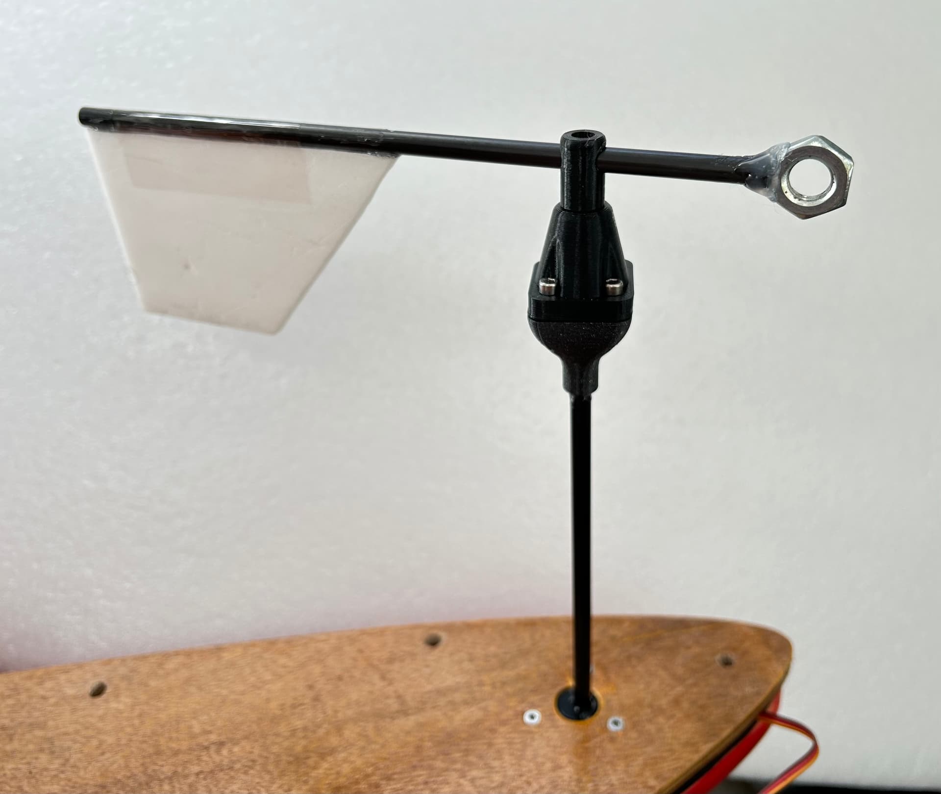
I managed to get the AS5600 working with its analog output. I’m using the common white AS5600 boards you see all over Amazon. Analog out only works if you remove the R4 resistor. Also, the specs don’t say it but these boards seem to work well at 5V. I’m running mine at 3.3V tho, as my FC analog rssi input is 3.3V. Using a simple RC filter with non-shielded wires and don’t seem to have any impedance matching issues yet. Will see how it goes
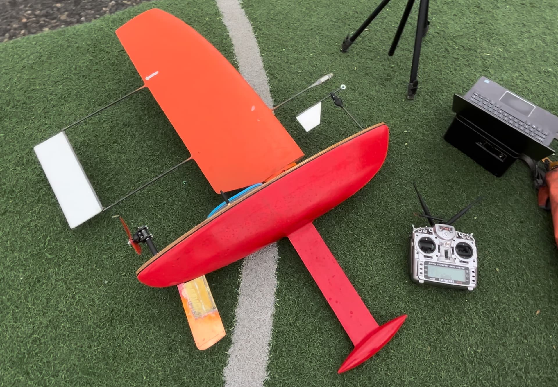
Tested out the new AS5600 wind vane at the lake today with @playertr and it seemed to works great!
Made some modifications to my boat including a super long bulb keel and larger rudder. Now sailing at 45 degrees off the wind seems like no problem. And its decently fast!
With pretty much all default parameters it seems to do a pretty good job running waypoint missions. Although its tough to say, because I have no experience with what a well tuned ArduPilot sailboat looks like. Moving forward, I have a few questions:
In the documentation I read “The servo min (SERVOx_MIN ) and max (SERVOx_MAX ) end points should be set such that the main wing is held in a maximum lift angle of attack on both tacks.” Is there a good way to find these values? I would assume it’s just manually sailing around and figuring out what elevator angle results in the highest speed? Would too much elevator angle result in the wing sail stalling?
Also, in high winds my boat has trouble carrying speed through a tack and sometimes starts to go backwards. Is there a feature that makes it do a 270 degree downwind turn (jibe?) instead of turning into the wind?
The key thing here is that lower elevator always means less lift so the heal controller does not get into positive feedback where reducing the elevator un-stalls the wing and actually heals over the more. If your after performance then yeah some manual testing would show how far you could push it before stall.
This is not currently supported, although we do have a open PR (which I need to review) for some tacking improvements. I see you have a motor setup, this should kick on automatically and help get it going again if it does get stuck in a tack.
@rctestflight The Sailboat “Get out of irons” PR is here. It is currently only designed to work for a traditional sail. Getting it to work for a wing sail shouldn’t be too difficult. Instead of sheeting out, maybe it should set the trim tab to max one way or another to get maximum drag and also use the wing to turn the boat.
I have a problem getting a Calypso Windvane (RS485) to work, but I do think it isnt related to the windvane itself. Let me explain.
I have set these parameters:
WNDVN_TYPE = 4
WNDVN_SPEED_TYPE = 4
Then after saving I go to the Data view / Status. The wind_dir and wind_vel start to display numbers. This is remarkable as at this point I do NOT have yet set a serial port to 21 (WindVane) and it’s even not connected.
I have no idea why it’s showing numbers, but I continu with setting up the serial port. I have a Herelink Air Unit connected to tele1, so I connect the Windvane to tele2 (with the TTL module in between).
I write the parameters, disconnect the power, connect tele2 to the WindVane and power on the AP again. The wind_dir and wind_vel keep on showing invalid numbers. They do not reflect the actual values from the WindVane.
When I connect the WindVane to a computer, I do see the NMEA0183 packets on boudrate 38400 coming in. So it’s confirmed it works.
I think my issue has nothing to do with the actual WindVane, but some other issue causing the wind_dir and wind_vel to show bogus data. Any toughts?
Hardware:
OrangeCube
Here3+ GPS (CAN)
Herelink Air unit (Tele1)
Calypso Windvane EMEA0183 / RS485 with TTL mod (Tele2)
The reported numbers are true wind speed and direction. The apparent wind speed from the sensor is 0. ArduPilot takes the apparent wind reading from the sensor and the vehicles measured speed from the GPS to calculate the true wind. So all your seeing there is the noise from the GPS position.
We do send back the apparent wind reading direct from the sensor, you can find them as “MAV_APPWNDSPD” and “MAV_APPWNDDIR” in mission planner.
The how exactly is the sensor connected? Do you have a level shifter?
has anyone tried to make an ultrasonic anemometer? I think modern chips are now fast enough that it could be done with a lot less hardware than these projects.
thats amazing, I knew it had to possible! im going to try and replicate, if I can make it work I’m going to try to make it smaller. I have a lot of small transducers that I have been experimenting with for sonar proximity systems.
Great idea. To make it smaller, you will probably need some higher frequency ultrasonic transducers ( Shorter wavelength) I found some 200 kHz ones, but never got around to doing it. Then obviously you will need a faster processor. If using stm32, it may be worth looking at one with a High resolution timer (HRTIM) which uses a PLL to make a clock at a higher frequency than the system clk ( 32 x as fast for HRTIM on eg STM32G474 for example).
Also to generate the pulse, think in terms of hitting a bell with a hammer. IOW one big pulse is better than a lot of little ones. The car reversing kit uses a pulse transformer, but you could create a reservoir of high voltage maybe ( say 100v) which might be less noise. The Big pulse hits first and then the nest oscillations get smaller, but at the rx this results in generating a nice square pulse as it all evens out. Anyway this is a great idea for a project so hope you persevere with it
There is a video on youtube where someone is using the fast ADC on a teensy to read the raw analogue input from the sonar and doing all the processing in software to look for peaks. I think that this approach could get around the issues with the limitations of the parking sensor board.
I would probably need a pair of teensy boards as they only have 2 adc channels.
Yep, probably nicer to redo the board. ( I liked hacking the thing onboard the existing pcb is all) But there is a Kicad schematic of the car reversing board and mods on the github link.
Oh yes. I used the comparator on the Atmegaa328 rather than an adc. I used it for threshold detection, then switched it to zero crossing ( so to get the zero crossing of the sine wave to use as the consistent timing point)
Actually since I did this a couple of years ago, things have come back to me. I remember ending up deciding that to make it smaller that the best option would be to use a digital low pass filter. So would need to look at best ADC to get adequate data rate. Havent used Teensy much so don’t know if its good or not. The STM32G4 has some errata on the ADC which is worth reading before going down that road


")