My god you guys are fast here 
It’s very annoying, but I have to spend so much time on my daytime work right now can’t test it. Last night at least I got your latest code successfully flashed to the board.
Tried some combinations of settings.
Since I only know for sure the volt and current pins are working correctly and what number they have, AD input 12 respectively 11, I decided to use them for wind speed input. ( I configured my volt/current meter before and got true readings.)
WNDVN_SPEED_TYPE set to 3
I assume the WNDVN_SPEED_PIN can be set to anything and will be ignored. It is set to 14 but the other parameters will need to be set from the RPM parameters right?
So, I have tried with
RPM_MAX: set to 600 from standard 100.000 that seemed unrealistic and might cause a slow spinning not to show up.
RPM_TYPE: set to 1 PX4-PWM as well as 2 AUXPIN
RPM_PIN: set to 11 and then 12 (manual say can only be set to 50 up to 55)
RPM2_SCALING: left to default setting 1
Then I spinn the cups and look in the Flight Data screen of MPlanner, in the Status window for some change in numbers. I don’t know where to look since there are so many confusing parameters, but I checked
. rpm1 and rmp2 at the way end of the list.
. wind_vel
. ecs1_rpm, ecs2_rpm and ecs3_rpm.
But no change in readings, despite all different combinations above.
Are my pins (11, 12) not in the scope of the RPM library?
Where should I look to see the wind speed?
Thanks a lot.
Thats the advantage of the sailboat stuff, we don’t have to worry too much about breaking things for loads of people as we do for the other codes.
RPM_MAX doesn’t really matter, its just used to try and detect a bad reading, so long as its a bit above your maximum expected should be fine.
RPM_TYPE you want 2 for auxpin
RPM_PIN the pin mapping to gpio can be found here. I would suggest using pwm 6 as its the last one on the pwm output bus. So this would be GPIO pin 55.
I think you will also have to drop BRD_PWM_COUNT by one or two, so set it to 4 for the time being.
RPM_SCALING you will have to calculate, I would guess what ever it defaults to will be in the right ball park. Keep in mind that if this is wrong such that its reporting outside of range of RPM_MAX and RPM_MIN you wont get a reading.
Then your data should show up as rpm1 and the same reading should be also seen for wind_vel. You can change the values in the quick tab in MP by double clicking and assigning them to any of the values from the status tab. Just makes it a bit easier to see whats going on.
1 Like
That was a very helpful post Peter.
The cup speedometer is working and displays in my quick tab now 
Will figure out how to calibrate it later for correct m/s, since my first wind vane,
the Hall non-contact sensor has just arrived.
1 Like
This wind vane unit is really offering close-to-zero resistance when turning it around. No need for ‘de grease’ it.
So far so good.
The problem I have is it does not seem to be recognized at all by the FC.
I know the selected pin is working, 55, since I successfully used the cup speed on the pin and it was okay.I have tried two things:
. power it with 5V - no sign of life.
. use a power step down to 3.3V
No readings or change when I turn the knob.
Possible problems:
. when powered with 5V the unit is working okay but the board cannot read results over 3.3v.
. when powered with 3.3V the pin can read it but the Unit needs 5V to work.
Or it could be anything else - I have no idea.
What you think?
I think you will have to use the voltage or current input pin for the hall sensor input. Again the pins are defined on in the hwdef.dat file, voltage pin is 12 and current pin is 11. Not all the pins gpio pins on the revo mini can do analog inputs. Looks like you have to power it with 5v but you cant put more than 3.3v into the pin so you will need a voltage divider on the output.
Thanks a lot Peter,
. for the wind speed calculation with the cups: RPM_SCALING calculation =
from RPM to Wind speed meter/sec:
Radius= 0.09 meter
Circumference = 2 x PI x Radius = 2 x 3.141 x 0.09
Anemometer drag factor = 1.18 according to their data sheet
Then divide by 60 for the RPM minute to m/seconds.
(0.5654 x 1.18) / 60 = 0.011119
RPM_SCALING = 0.011119
The readings I got seems to be in the ball park when blow wind on it. however likely need to compare the reading with another independent anemometer.
For the wind vane direction, it seems a bit more complicated.
Yes, using AD pin 11 for batt currency, sacrificing the current reading for the benefit of getting wind direction.
Its clear that even if I power the unit with only 3.3 volts it will still output 5v maximum (using the calibration function). So the output of 5v is not good for the pin 11 who can only read correctly 3.3v. So I think I need the fix Peter suggested, but I do not understand:
Where to get this voltage divider? any idea ?
Thanks a lot
/Karlitos
This caculation seems right, as you say hard to tell without something to compare to.
A voltage divider is just a couple of resistors, I attempted to explain in the wiki here: Wind Vane — Rover documentation
But re-reading it maybe I didn’t do such a good job, i think there is a hand drawn diagram in the tread somewhere.
edit: i found the diagram, it doesn’t apply to this case. Sparkfun have a nice tutorial and happen to use 5v to 3.3v as a example.
I read the wiki and I found the diagram and I got confused.
That does not mean you didn’t do a great job, only means I am easily confused 
At least I understand the problem can be solved.
I will study that article (at first glance it looks a bit intimidating though).
Thanks
Success 
Studied the article, and this is the circuit that worked for me
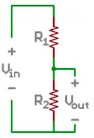
I purchased a whole pack of resistors but used these ones:
R1 = 1800 ohms (close to plus pole)
R2 = 3300 ohms (close to minus pole)
V out to the PIN 11 and should bring it to around 3.2V (definitely less than 3.3V)
Even though the volt from running WNDVN_CAL ends up with WNDVN_DIR_V_MAX = 4.9V, the flight controller can read it correctly and gets 0, 90, 180, 270 degrees just were it should be. The wind direction is working. So I think it’s some kind of volt reading discrepancy depending on the ground used. I will not bother much with it.
But maybe I should?
Next, I finally received the Bourn unit and that also works.
Unfortunately I got the product 6630 S1D and not the 6630 S0D, this means my unit do not continuously turn around but stops after 360 degrees.
Anyway it does work fine with same R1 and R2 setup as the other unit.
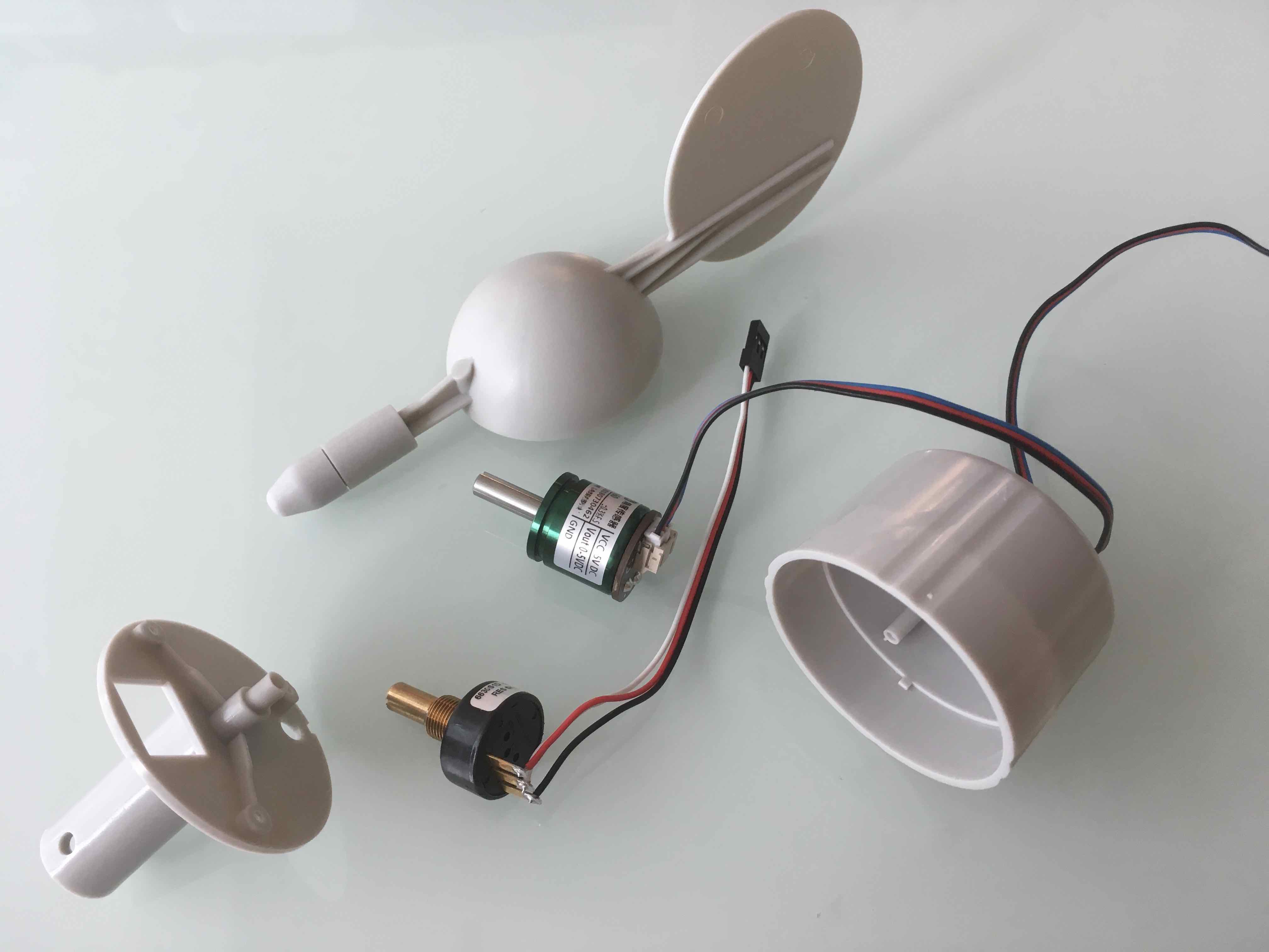
However, it really need a lot of force to turn it around. And to open it to ‘degrease it’ seems very difficult to me without breaking the housing.
Unless anyone ask me, I will skip to get a new S0D version unit, since i will still need to ‘de grease’ that to make it work. I do will try if there is a need though.
Now will try install the Hall non contact sensor in the wind vane housing.
1 Like
if its working OK i wouldn’t be too worried
Yesterday my independent reference, a little handheld anemometer, arrived and I tested it today to compare readings. I used a hairdryer to create different wind speeds.
The results verifies that my Cups as well as the RPM factor I used are all okay.
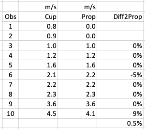
Less than 1% difference, if omitting the low wind speeds the propeller based handheld anemometer could not pick up.
Success ![]()
1 Like
Unfortunately after waiting long time for delivery then I killed one of my rfd900+ telemetry/ppm units with applying 12volts by clumsiness. 
at the moment I only have a Bluetooth link for telemetry so I want to complete the build before taking it out to the lake. So still need wait another week.
The Hall type wind vane is now installed in the housing. It was easy just using a drill two screws and hot glue. The housing is easily attachable and detachable to the boat for transportation.

1 Like
I have a MicroSD board and was thinking to add it onboard for logging ete.
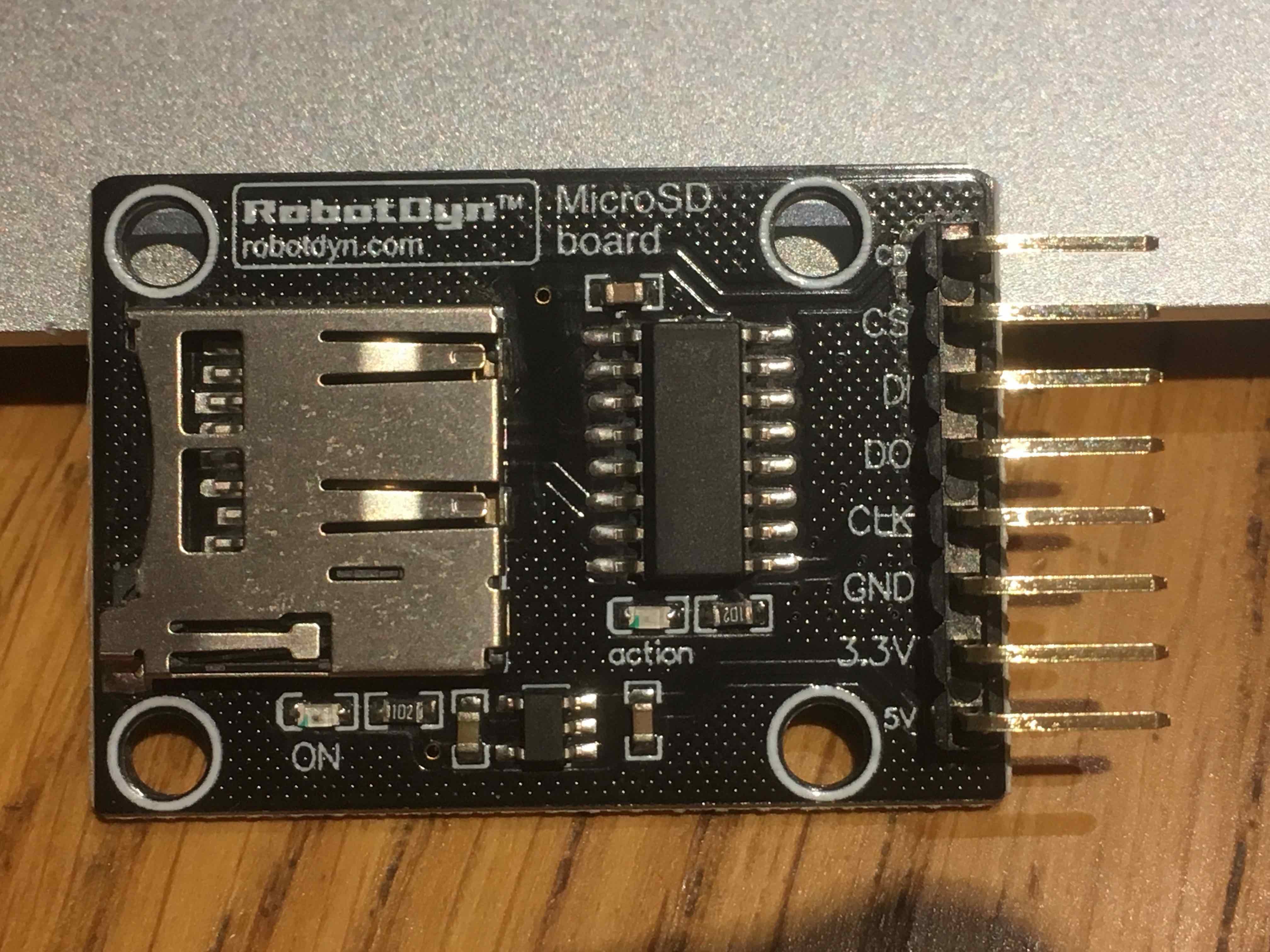
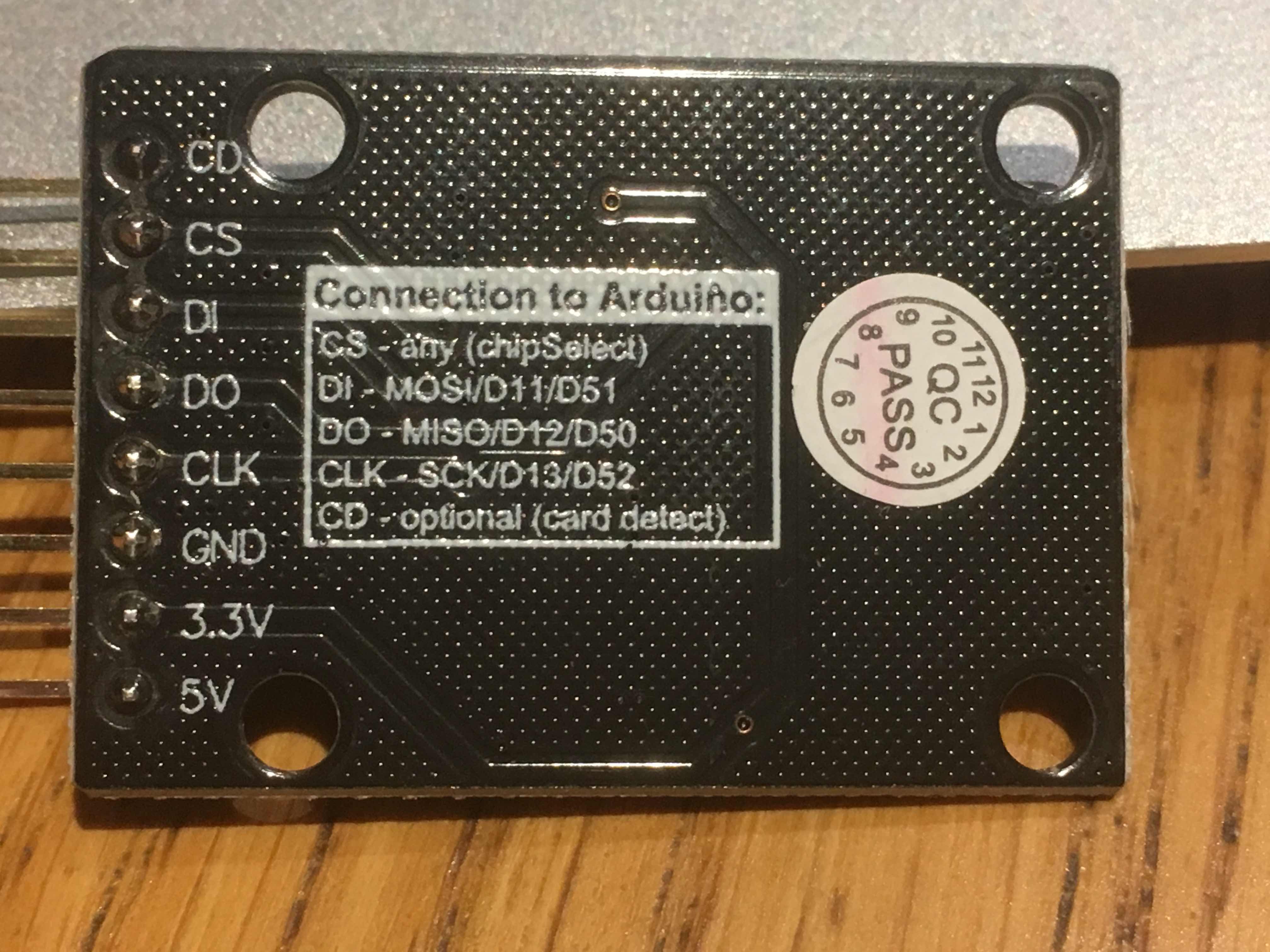
Peter, you pointed me to the hw definition file already, but it’s difficult for me to understand it. The manual say " * RevoMini’s OPLink port can be used for external SPI periphereals connection". Buy it seem to require compiling custom firmware based on changes to hwdef file.
Any suggestion here?
I am also looking to add one more analog pin (for lipo current sensor).
looks like the SPI bus is setup for the SD card by default. I’m not sure how to hook it up, i think there is a thread on here somewhere with more information, or on RC-Groups. I think your out of luck for another analog pin though unfortunately. Current is not so important on a sailboat, its not like your going to be using lots. I think your only other option is a different flight controller.
Okay. Thank you. Will research it more.
Hi all, my team and I are undergraduates at UC Davis, and we’re working on our senior design project, which involves assembling an autonomous control system for a model Laser class sailboat. We purchased our first Pixhawk (CubeBlack) recently, and, after installing Mission Planner and following the instructions here, we’re wondering what the next steps are exactly. For example, is the firmware discussed during the “Initial Setup” portion of the aforementioned tutorial all we need to upload to Mission Planner prior to testing? We found this directory as well and are wondering what relevance these files have to our needs. None of us are familiar with Ardupilot/Ardurover, Mission Planner, or Pixhawk; however, we are very eager to learn and would be very happy to share the results of our project upon completion this June.
welcome,
the first thing to do is to read through the setup wiki.
http://ardupilot.org/rover/docs/apmrover-setup.html
then the sailboat wiki.
http://ardupilot.org/rover/docs/sailboat-home.html
and the windvane wiki.
http://ardupilot.org/rover/docs/wind-vane.html
Unless you want to use a ‘cups type’ anemometer you will be fine running the stable release. This is what you will get when installing rover with mission planner.