I think the only reason this would happen would be if the ekf is not happy. Are all your arming checks on? If you switch them all on and try and arm into acro it should give you a more helpful message.
I think Rover-3.5.0 is appearing as the default version for Rover now so hopefully that issue has been resolved. If not I can look into it further.
No no, no need thank you, solved by upgrading the mission planner.
Thanks a lot!
Peter, about getting in to Acro mode to test how the sheeting will behave when changing boat heading around indoors…
I had set Always armed, and now changed it to normal arming (throttle down, rudder to right side). It now responds with these messages when I try to arm:
PreArm: Board (3.3v) out of range 4.3-5.8v
PreArm: RC9 minimum is greater than trim
PreArm: RC8 minimum is greater than trim
PreArm: RC7 minimum is greater than trim
revo-mini 003D002E 35355110 31313931
ChibiOS: 35ad8a79
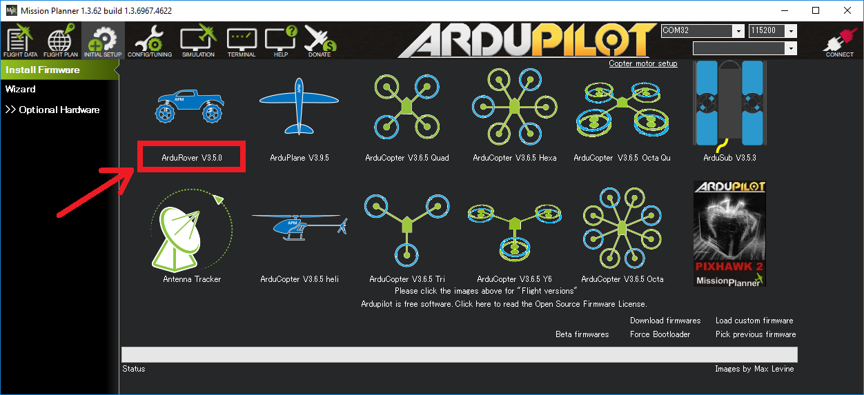
ArduRover V3.5.0 (af36fc5e)
First one means some power supply to the board or a pin is not okay?
The other ones, The RC7, 8 and 9, they are not used, not sent from my RC TX. Only sending out 6 channels. Does it prefer more channels?
And a last question - is it at all possible to test the Acro mode without a gps?
(cant get outside and get a 3d fix for some weeks)
power supply to the board I think
This is a bug with mission planners calibration. You will have to go into the full parameter list and set RC9_MIN to 1100, RC9_MAX to 1900 and RC9_TRIM to 1500. Also for rc8 and 7.
Yes.
you can always disable arming checks if there stopping you arming using the ARMING_CHECK parameter., you can disable the board voltage check. Its not recommended to just turn them all off, try to turn of as few as possible.
Thanks Peter,
I checked the voltage with a multimeter on the power source and at different points on the board, gps, rx and it shows between 5.13 - 5.07volt so I dared to just turn the board voltage check off.
The CH7, 8 and 9 warning disappeared after using your tip.
Now it can arm if mode is in Manual. But then when switch to Acro will fail with the msg: need position estimate.
I assume it need some Home location and that will be solved with first GPS 3d fix. Likely also can be set manually somewhere. However I moved on and tried to skip all arming checks for now.
Then it can arm when mode is in Acro. Good!
Something very unexpected happened when turning the boat around from North, where it was armed, so it think wind is from North. I was thinking Acro mode would let me control the rudder manually and the FC would adjust the sail depending on the wind. However, it does not. It is adjusting the rudder. When turning boat to right then FC do rudder compensation to the left.
I should mention that in Manual mode both rudder and sail can be nicely controlled by my radio input.
Any idea what I do wrong?
This is correct, in acro mode rather than inputting a rudder angle you input a desired rate of turn and the flight controller matches it with its PID gains. So when you turn the boat to the right its trying not to change angle so steers to the left.
Good, so the rudder logics is working, keeping the course.
Can you suggest How I can test if the logics of sheeting the sail is working?
At the moment I do not have a wind direction sensor and I do not have a gps fix.
the sheet should work as the rudder does in acro. if you arm facing north in (heading when armed wind vane mode) and turn it south it should sheet out.
oh and I should add you will have to bump the throttle, at minimum throttle it will just stay sheeted out. Any throttle above min and it will do auto sheeting
Aha, yes sheeting did not move at all.
Then tried bump the throttle, but still no motion at all turning from north to south.
When I have minimum throttle then the sail is fully sheeted in, not sheeted out.
Should I set it the other way around, reversed?
This is correct for manual mode, for acro minimum throttle should be all the way out. The does the flight controller realise its yawing round, ie does the yaw change in mission planner? You will have to turn a far way before it starts to sheet out, maybe 30 deg, i don’t remember what we set the defaults too. But at 180 deg it should defiantly be all the way out and 0 deg all the way in.
1 Like
Success 
Its arming in Acro and both sheeting and rudder behaves as expected.
I redid the setup from beginning with calibration of accelerometers and compass.
Set up wndvn_type 2 with offset from arming heading on a nob on the transmitter, plus a switch for manual tacking. Following the wiki was clear no problem.
If going sailing now (without windvane) would already be at a new level.
Waiting for delivery of those units though.
Thanks a lot!
2 Likes
still ice on my lake here…
if all goes well maybe put the rig and fc on a frame like this after the summer 
speed will be some 10x faster so really need a working wind vane and a windspeed sensor.
Way back in August, but there has been no real follow up o this interesting post.
I hope you still on to this?
Yes, polar plots holds promises. I was researching the Laser community to see if they use them and what they think.
For RC boats, nothing.
But for the full Laser size, this picture I think illustrates the mindset still prevailing on polars:
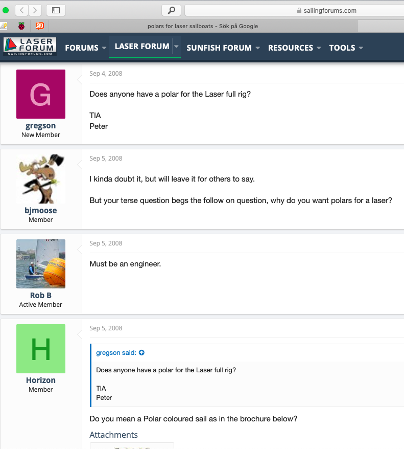
It turns out, they do have polars for Laser, but commonly regarded as useless because Polars do not take in consideration the crucial wave/sea factor. A wave will stop/alter everything for a small light boat like that.
I had two thoughts after learning this.
. We don’t need to consider the waves for RC boats since we mostly sail on ponds, rivers, lakes with no waves anyway.
. But, if we take the RC boat out somewhere else, even small waves will quickly matter for us. So, maybe develop something like ‘Wave Polars’, using the fact that we do have accelerometers on board?
Add a 3rd dimension to angel and speed, like a z-axis, recording the change in acceleration (pos or neg).
Going upwind in different angels should result in negative acceleration pattern due to “stomping in to waves” (if waves present) and downwind positive.
Just an idea, It should be very helpful to decide if to tack or not?
Having read the wiki and this complete thread a couple of times now.
It really stands out is how a simple and straight forward code like this can manage such a complex task as sailing a boat. And it was developed so quickly. I believe in the 80/20 rule of things and think this version 3.5.0 is doing the most important things and doing them pretty well.
Maybe next steps, addressing the remaing 20, could be expected to take longer and be much more of a challenge ![]()
Learned there was some delivery issue with the Bourn unit so it will not ship until another 2 weeks. However, coming week the other unit should arrive, plus a new telemetry and gps unit.
I have done a small amount in this direction but not much. If your keen to do some testing I could pick it up again. Randy wrote a sailboat SITL to test with. I think there is a vid in the thread of it some where. I then palyed with the physics abit and wrote a matlab tool that finds the polar. ardupilot/libraries/SITL/tools/Sailboat_VPP.m at master · ArduPilot/ardupilot · GitHub
This gives a polar plot for a range of wind speeds.
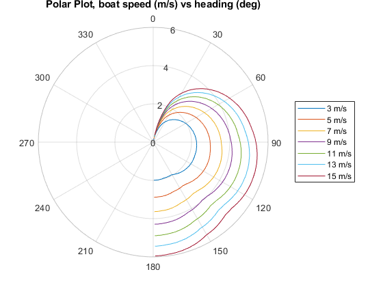
So there is a correct polar for the SITL sailboat. This gives our polar finding algorithm something to aim for.
Yeah something like this should be quite straight forward given all the sensors we have, maybe this is the next step. To give the sea state a score then each polar can have a sea state its associated with.
Then there are two jobs.
-
write the tool that finds the polars
-
add code that used the polars for navigation
They both rely on deciding on a format for the polar files and some where to put them. Unfortunately for you with your mini revo I think there is too much data for parameters so it will probably be on the SD card.
I would quite like to do some sort of continuous learning scheme for the polars, then we could just start using a default one and correct it as we go. If we have to have a dedicated training period it would take many hours in each sea state i would guess.
1 Like
But that’s fantastic!
Yes, I saw Randy’s sailboat software in the loop post.
This is all way over may skill level - i have never used the SITL thingi.
Need to read up and study a lot more before make use of this.
At the moment my focus is very basic 
to get two kinds of wind vanes installed, working and compare them and report back.
Then I think I will need ask you for some help making code support of a Cup type Anemometer, since I do not have more than 4 ATD pins, 2 for Volt and Current and 2 for Wind direction and Wind speed. The speed unit currently supported needs 2 pins. The Cup Anemometers type just need one pin.
To make a generic Cup Anemometer support I think only two parameters needs to be added:
. the radius of the cup from center = in the Argent Data System case 90 mm
. the ‘anemometer factor’ (compensating for the drag by the cups) = in the Argent Data System case 1.18
This page has the description, sample code and link to the data sheet.
https://projects.raspberrypi.org/en/projects/build-your-own-weather-station/6
B t w today my new gps arrived.
It’s half the size but seem to have double the reception of satellites.
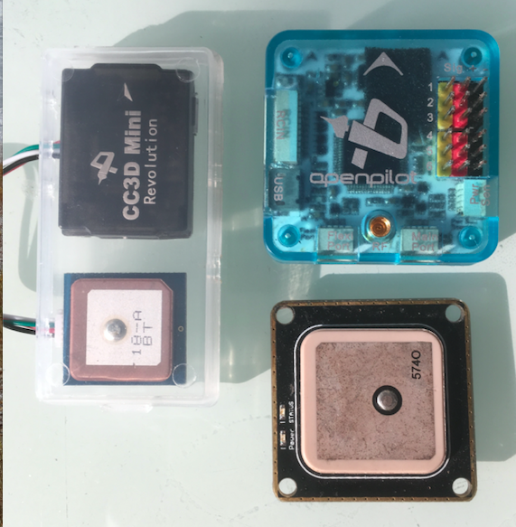
I got 3d fix and 8 used sats with 1.4 HDoP indoors with hopeless conditions of 35 stories buildings to the west, north and east. Flashed Ardurover successfully to the little Revo mini guy to the left. The standard size gps to the right could to 3d fix at best ever with 4 satellites from the the same location.
Yes, I will look in to the SD card options, it seems its supported at least.
Thanks a lot!
The first step in that direction is to get the sensor working with the RPM library, there is not much documentation but there is some here Complete Parameter List — Plane documentation Once you have that working we can just read in the rpm to the wind vane library and apply the scale factor.
Cool. Let me check it and try.
Have done a fix for this, its now in master and will appear here when it does the next auto build.
You can set WNDVN_SPEED_TYPE to 3 and it will take the rpm from the first RPM sensor. You will a have to add the ‘anemometer factor’ in to the RPM_SCALING calculation such that it gives the wind speed in m/s.
The code is completely untested but hopefully will work fine, would be great to have a picture of the anemometer fitted to your sailboat for the wiki once you have it working.
1 Like


Thanks, your picture is now on the wiki
http://ardupilot.org/rover/docs/wind-vane.html#rotating-cups-anemometer