For example
is there a good solution with a reduction at the moment or a bad one because the software will soon no longer (or even already) allow you to load openpilot sailing ?
For example
is there a good solution with a reduction at the moment or a bad one because the software will soon no longer (or even already) allow you to load openpilot sailing ?
Hi all,
A script to allow using CALYPSO’s Bluetooth windvane has just been added. No more need to run cabling up the mast!
Not tested in the wild yet, but seems to be a nice compact and light weight solution for smaller vehicles. Script and instructions here:
If anyone knows of any other Bluetooth wind vane / weather station type things that might be suitable I’m sure we could add support in a similar way.
Hi,
I met these people at the exhibition “boot” in Düsseldorf.
https://open-boat-projects.org/en/
They have a wind sensor project with wifi NMEA0185
https://open-boat-projects.org/en/zusammenbauanleitung-windsensor-yachta/
Also available on gitlab
https://gitlab.com/norbertwalter67/windsensor_yachta
Would be great, if this could be connected to ardupilot.
@iampete
Hi Peter,
I’m using matek f405-wing, and P3022 sensor as windvane.
I want to connect the sensor’s analog outpin to RSSI, which is the correct value of WNDVN_DIR_PIN?
I find the hardware definition, the pin 15 is the value.
Rover Sailboat working:

The flight controller sails it better than I do ![]() Great fun and am looking forward to doing more with it. Thanks to everyone involved in putting it together.
Great fun and am looking forward to doing more with it. Thanks to everyone involved in putting it together.
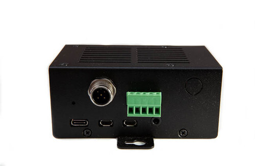
The flight controller is a classic OpenPilot Revolution. I had to use an external compass and I also decided to add an analog input for the AS5600 analog wind direction sensor. I found it relatively easy to make a custom hwdef for it froma servo output . That is certainly a nice feature of the Chibios HAL.
The boat itself uses a balanced sail ( centre of effort close to the mast rotation point), which means that a relatively small and fast servo can be used to sheet in and out. This is very successful and in ACRO mode the boat can track changes of apparent wind very responsively.
One issue is that the code assumes that there is a linear relationship between servo position and sail angle. In fact even with a winch there will be a variation, and with my setep, I calculated there is about 6 degrees non-linearity in the 45 degree position. I wonder if a few intermediate [angle,pwm] points ( maybe 2 or 3) could be used to provide a closer relation between sail angle and pwm with interpolation ( either linear or a spline)?
I found the default transmitter logic in the ACRO mode unintuitive. Most model yachtsmen I know push the stick away to let the sail out and indeed this is what happens in manual mode I think? In “ACRO” mode originally I think the throttle acts as a simple switch, where pushing throttle away ( above 1500 usec) sets the sail to its ideal angle of attack SAIL_ANGLE_IDEAL and pulling it in sheets it right out?
I tried a different logic, where in ACRO the throttle acts to change the angle of attack . Pulling the throttle right in sets SAIL_ANGLE_IDEAL and pushing it out most of way ( say 90% of range) sets angle of attack at zero, then the last 10% sheets right out. Now you can use the throttle to proportionally change the angle of attack from 0 degrees to SAIL_ANGLE_IDEAL in acro mode and by setting a larger SAIL_ANGLE_IDEAL this can be used to find the best angle of attack at different points of sailing , seeing how much before the sail stalls. (You can also dump the sheets in emergency, hough you could just switch back to MANUAL mode I guess)
Anyway the Rover Sailboat is great , especially since I moved near a nice big lake! and I look forward to doing much more with it.
Good morning,
I find that being able to use an open pilot recolution is great, the price is within my reach.
I plan to use a BNO080 as a compass and an AS5600 as a wind vane but with a wing sail with tail like Saildrone
Could you give a newbee details of the program modifications, ey how to fine tune it in the parts that differ. This is my first use of open pilot
Thanks in advance
Cheers
fr
Looks like you have it working nicely, always great to see some more sailboats!
RE: acro, its speed controlled mode so more throttle means go faster and less means go slower. However sailboats don’t do speed control, there either trying to sail or not, so the throttle becomes a on/off switch. Your right its a bit odd if your used to other model sailboats, or sailing in manual mode, but it is the standard ArduPilot behavior across all vehicle types. We do also support sailing and engines, which case doing it the other way would be very odd.
RE: sheet control. We could add “calibration points”, however it would make the setup more complicated and add loads more parameters. My preference would be to add some way to input geometry we might even be able to do it by default. The code’s linear interpolation is sort of like assuming the sheet takes the circumference, actually the sheet goes in a straight line. With a little trigonometry I think we could take this into account. Something like this should work:
mainsail_base = (safe_sqrt(2 - 2*cosf(mainsail_angle-sail_angle_min)) / safe_sqrt(2 - 2*cosf(sail_angle_max-sail_angle_min))) * 100.0
We should also probably apply the PID to the angle rather than the mansheet…
@fra53 The modifications involve building a custom version of ardupilot
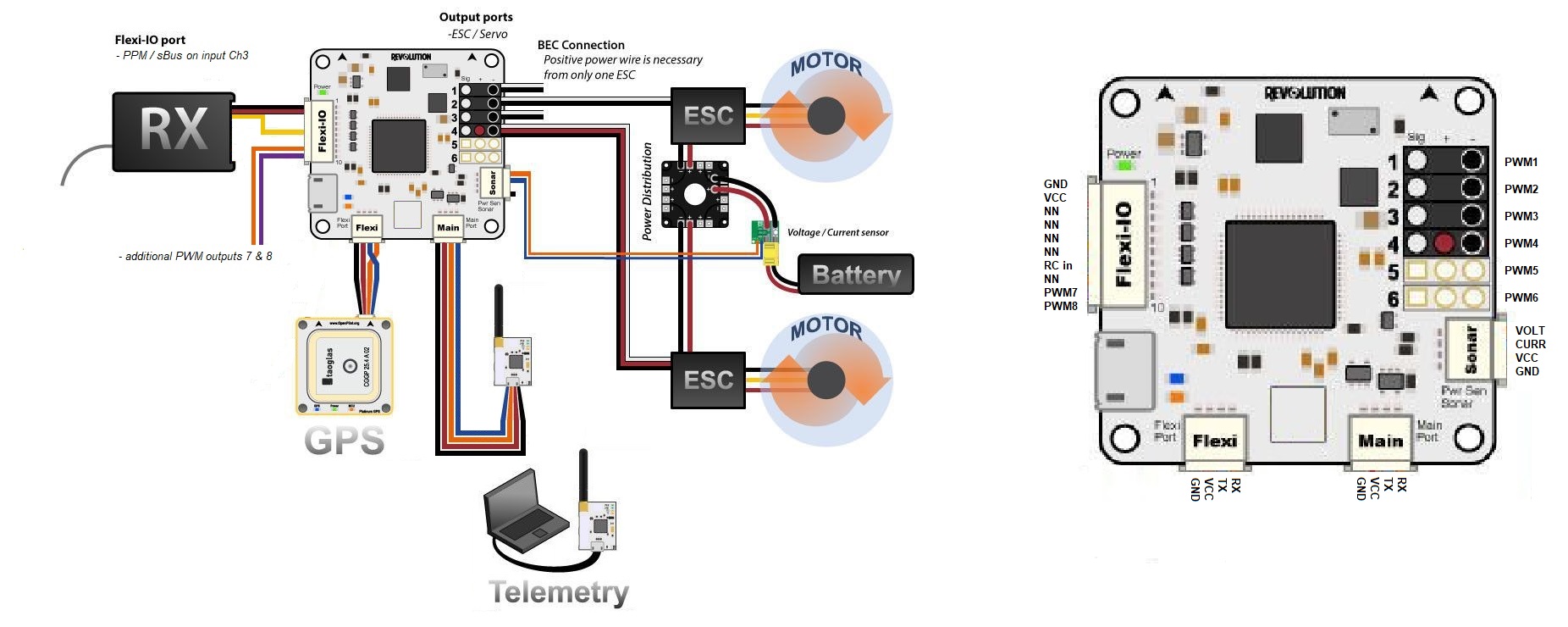
If you havent experience of building ardupilot, I would suggest just getting the master version built and working first on a simple car or power boat as described in detail in the Official Ardupilot documentation. Once you get that working and tested you just add a new subdirectory in AP_HAL_CHIBIOS hwdef.dat file as linked above https://github.com/kwikius/ArdupilotSailboat/blob/andy_revo_sailboat/libraries/AP_HAL_ChibiOS/hwdef/revo-sailboat1/hwdef.dat. Waf should find it I think for building. Then once you uploaded that version the pinouts will change as shown below.
The external magnetometer may not be necessary, but I found the on board one very noisy and caused the EKF to complain ( though this was on my original electric test boat)
I also found it necessary to cover the onboard baro with some foam to prevent the EKF complaining about height changes on every air current that passes.
My version of Ardupilot is quite old, but I would guess latest master should work OK unless there are mods to the AP_HAL_CHIBIOS hwdef format.
flexiPort (4 way JST-SH ) → I2C ( external magnetometer)
mainPort (4 way JST-SH) → Telemetry usart to 3DR telemetry radio
PWMOUT ch1 → Rudder servo
PWMOUT ch2 → power in (Just found it convenienet for a 5V power in dupont connector)
PWMOUT ch3 → ESC/ mainsail
PWMOUT ch4 → Analog wind direction sensor
PWMOut 5,6 → GPS USART (signal pin of pwmOut6 TXO from FC, signal pin of PWMOut5 RXI to FC)
PWR Sonar ( 4 way JST-SH ) → Battery voltage via resistor divider on pin 4)
FlexiIO ( 10 way JST-SH) → RC input on Pin 7 ( Radiomaster R81) ( remains as shown on https://ardupilot.org/copter/_images/revolution_wiring.jpg)
@iampete In a pure sailing boat the throttle is the angle of attack of the sail. I found it useful to be able to vary it, while still allowing the FC to control the angle of attack firstly so you can gradually slow the boat down by depowering it without going back to manual mode ( so you can avoid bumping into other boats for example) and secondly so you can play with the actual angle of attack to find out where the sweet spot is ( in which case you would increase the SAIL_ANGLE_IDEAL parameter to some larger amount where the sail stall and then gradually adjust the angle using the throttle till you get the sweet spot)
Regarding linearity of the sail angle , I think you are assuming a winch with a drum, but I have a servo with a sail arm rather than a winch so there is another non linearity. I added an OpenSCAD file ( with extension changed to txt to allow forum to upload) showing the arrangement on the boat in the video ( ignoring 3d ) the servoPulse variable changes the geometry and outputs the resulting calculated main sail angle in the console. You can use the openscad customiser to change the servoPulse variable for visualisation.
sheetCalc_scad.txt (3.1 KB)
Of course there are many other possible geometries. A spline with control points might be a more general and more flexible way to describe the function than attempting to find a simple mathematical function to cover every geometry. You don’t need that many points to make a good curve, but more than 2 ![]() Anyway sail angle of attack is quite a critical measurement, especially as sail boats get faster.
Anyway sail angle of attack is quite a critical measurement, especially as sail boats get faster.
THANKS.
It is not won
We could do this with the sailboat specific mainsail input function, its a bit like the “throttle mixing” we do with the throttle on planes. I don’t think we can do that for the throttle input, its position already means speed even though we don’t do speed control on pure sail boats yet.
The problem with a general solution is that everyone will want to use it, so we will have to implement in a general way. Plane control surfaces for example, or helicopter swashplates. Say we add an interpolation type parameter and two more points to go with the min/max/trim we have already. That is 3 extra parameters per servo output, we support up to 32 servos. So that adds 96 new configuration parameters. That means more flash, more memory, more cpu and longer parameter download times when you connect a GCS. That cost might well be worth it, but we would have to decide for the project as a whole. If we just add a geometry parameter for sailboats it has minimal impact on everyone else so we can do (more or less) whatever we like.
In both cases the conflict is between what would work great for the sailboat code on its own, both of your suggestions would be great there, and what works for sailboat as a (quite small) part of ArduPilot, we try as much as possible to keep consistency between the vehicles and make upgrading to new versions easy.
“The problem with a general solution is that everyone will want to use it.”
If everyone wants to use it that would seem to be a worthwhile thing ?
To make this a more general solution, then you don’t need to apply a separate set of curve parameters to every servo output parameter set from 1 to 32. You could have some unassigned interpolation curves sets in parameters. Then your “in the know” actuator can request to use a particular curve for your mainsail, flaps, flibble, or what you will. (Curve is read only I assume, so one curve could be be used for several actuators too, e.g for ailerons and flaps).
If you aren’t happy creating more parameters, you could abuse some of the 32 servo channels for curve x,y pairs, say using their minmax values as curve fit x,y pairs ( or use battery, temperature or osd parameters as there are also quite a few of those that might be spare). Now you could add a servo function enum “This is a curve parameter” or some such to some sequence of servos, say working back from Servo32 and then work back including any that have the function listed as curve_parameter as part of the curve. You could get up to 29 points on my sailboat with that approach, though I think maybe 3 or 4 points would be fine to get much better accuracy than my current 5 degree error at half way
Anyway I guess I should just get on and see if using a curve actually makes a difference in practise.
Thanks anyway for the work on the sailboat. I’m also hoping to try and setup some downwind gybing like the Americas cup AC72 do, rather than running straight downwind. The wind vane on my boat is at the front and running downwind doesn’t work too well as the vane flaps around when masked by the sail and moves the sheet in a potential positive feedback loop! ( Each time sail goes through the wind up or downwind presumably sheds the starting vortex. I could move the vane but I am hoping to make a a new boat where downwind gybing will make more sense. The only question is what happens as the boat gybes when the vane will go wild again I guess! It may be necessary to have more than 1 windvane and figure out which to use based on the current wind direction.
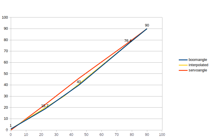
EDIT. I added result of adding one point to the curve with linear interpolation. Red is angle according to servo blue is boomangle based on the openscad script above( 2 end points and 3 intermediate points drawn in openoffice as linear interpolated). yellow is the interpolated angle based on one interpolated point at [35,30] ,which brings the error from 5 degress below 1 degree at max
Could anyone point me in the first direction here, I have a decent amount of knowledge with NEMA2000, NMEA0183, SignalK, Openplotter but just starting out in the Ardupilot firmware world…
Looking at the possibility of writing an Ardupilot CAN driver to support NEMA2000 utilizing Timo Lappalainen’s lib. The goal being a plug and play Ardupilot onto a standard marine NMEA2000 (Can) backbone network exposing a vessels instruments and controls to the Ardupilot and vice versa.
Routing the NMEA2000 data and configuring the Ardupilot correctly should allow the same control of a vessel as we have for the small scale sailing drones.
This is currently the situation with OpenPlotter (RBPi/SIgnalK) where I can plug a Pi directly into the backbone via NEMA200 which includes drawing 12v power from the bus (see 5pin NEMA2000/DeviceNet connector). This allows OpenPlotter access to all the ships data along with controlling the autopilot etc…
NMEA 2000 is a little tricky because the standard is not public. But we can certainly add some level of support based on existing libaries.
The easiest way to get something working would be to use lua scripting, it is a great way to add support for new can protocols. For example this motor protocol:
Or this more complex gimbal driver:
I’m using main sail parameter to drive a hard wing. Worked great until I hooked up last night inside the vessel. Now when wind is at 359, wing is a 90 degrees. I read something about the ekf thinking its going backwards. Would that do it? the pixhawk mounting position has an inclination of about 5-10 degrees. BTW thank you to everyone on here. Been picking through this chat for weeks to find little helpful gems.
classicwindvane.param (14.6 KB)
it seems that the sail mast rotation works perfectly if i add a 180 degree offset to the wind direction. Anyone know how to remedy this? attached is my params list
If it works with a 180 offset than that is probably correct. You can check the reading in the GCS. It will report absolute wind direction but what you want is relative angle to check the wind vane. You can either move the vehicle until its yaw is exactly 0 such that relative and absolute angles are the same, or find MAV_APPWNDDIR in mission planner to get the value directly. It should be 0 when the vehicle is “head to wind”, that is the wind coming from directly in front of the vehicle.
i should have specified that when the wind reads 359, the sail is perpendicular the vessel. When the wind is at 180 the sail is in line with the vessel and will trim properly within a certain range. Its as if the sail is trying to sail backwards (rotated 180 degrees).
Huge fan by the way!
this sounds silly but is it possible that the vehicle being turned away from its waypoint is causing this behavior? Its the only thing i can think of that may have changed.