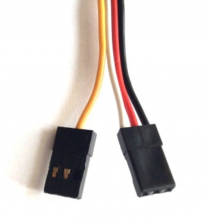
My HobbyWing V4 60A ESC has an RPM signal wire.
Is this signal of any use for ArduCopter?
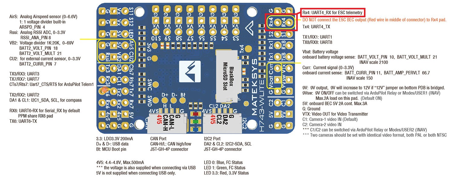
Should it be installed as shown in the image below, somewhere else, or not at all?
My HobbyWing V4 60A ESC has an RPM signal wire.
Is this signal of any use for ArduCopter?
Should it be installed as shown in the image below, somewhere else, or not at all?
If you are talking about the 4th wire rpm output and not the other 3 wire telemetry plug you should be able to run it to one of the unused s pins for servos or GPIO. I have done it that way to get the rpm in Ardu for my 25a align that is a rebranded 25a hobbywing platinum v4.
I found the docs a little unclear on how to configure for this, but I’m sorta new to ardupilot. In RPM Measurement — Copter documentation
The “Electrical Commutation Sensors” section is what you want and that will just point you to the “Hall Effect Sensors” configuration above for actually setting things in the auto pilot but adds some detail about how to use it with that type of RPM output sensor.
The wire I’m referring to is the yellow one shown below.
I did read the RPM Measurement section, and I believe that this is the relevant part where it states “Connect all ESC telemetry wires to a single serial port’s RX pin on the autopilot…”.
I’m so new to this that I don’t want to damage anything by making a wrong connection.
If it is useful (and unharmful) to connect it on Rx4, then I’ll isolate the red wire and install the yellow one in it’s place.
Yep, thats what I was calling the 4th wire (the yellow). You will want to run that to GPIO like I describbed above.
Id use S11 or S12 if it was me.
Thanks spova.
What’s confusing to me is, if the wiring layout for the controller and the wiki both say to connect all ESC telemetry to an RX, and if the RPM output wire from the ESC isn’t considered telemetry, then what is?
The yellow 4th wire isn’t full telemetry its just the RPM commutation pulse thing. All the processing of that is done on the AP.
Telemetry is sending the actual data is some protocol/format and can include more than just RPM. It can include things like amps, temp, battery voltage as well on some esc. Its processed and turned in to data on the ESC then sent as that data over the programming lead to the FC. On the Platinum V4s I have read the programing port can carry telemetry.
This doc from spirit will give you an idea HobbyWing Telemetry - Spirit System Manual
I have not tried to get that working in my setup. I could not find a lot of info about how to configure it for ardu and my 25a didn’t offer any info I needed other than RPM since I was getting bat voltage on the main board, had a sensor for amps and was not worried about esc temp.
TLDR: Yellow wire just a pulse in time with motor spinning not a formatted signal. Programming lead carries a bunch of telemetry data in some unknown to me format.
If you do go with the programing lead telemetry route please let us know here the config details of how you get it working. If you just want RPM though I found the RPM wire to GPIO to be a much simpler option plus it uses a GPIO pin instead of a UART and in my case I had more free GPIO than UART so that was a bonus.
Mike, esc telemetry follows a communications protocol and that is why ESCs capable of telemetry are connected to a UART on the controller. In the case of the hobbywing (based on what I am reading in the wiki) it does not provide telemetry in the manner that I described above. Instead it is just pulling the voltage high and low for each commutator similar to a Hall effect sensor. So it is really just an analog voltage going between 0 and 5 volts to indicate passing of a commutator. The RPM is calculated based on the time between the edges of the rising or falling voltage
Thanks a lot for the info guys!
I’m going to have a lot more questions as I go along getting started with this stuff.
![]()
Feel free to ask your questions. I always learn something new from the following answers.
We, who read the answers, also learn.
BR
Heri