Try setting SERVO13_FUNCTION to GPIO first, before getting an Arduino. Then try swapping the pins about with that config. You can probably figure it out that way. If it is still not working, then I think it’s time to really figure out which pin is which on the sensor to have another “known” in debugging.
now have made both SERVO13_FUNCTION and SERVO14_FUNCTION to -1 for a GPIO…
rpm1_type = 2 for GPIO
rpm1_pin = 54 for aux5 on the cube
rpm1_min = 1 just to check if it reads 1 revolution
ICE_RPM_CHAN= 1 to read from the rpm1
tried the above and turned the prop by hand after powering up the engine ignition module but HUD still read RPM1: -1… so i think i will have to get the sensor wires issue sorted out tomorrow…
Be aware of the following when testing:
- the RPM library will not consider one pass of the magnet as 1 Rpm. The measurement is done by first counting the number of interrupts (times the magnet passes the sensor). That number of interrupts is then divided by the time period the interrupts were counted over (plus some other maths for conversion)
- There is a signal quality calculation done which looks at how much the Rpm signal has changed since the last reading. Your min quality is set to 50% so a change in reading of more than 50% is considered a non-physical reading and therefore unhealthy.
I only raise this because, if you are turning a gasser over by hand you may not be getting a consistent enough reading to actually get an Rpm reading.
1 Like
Matt… thanks a lot… things are reading perfectly now… got the details of the signal wires from the manufacturer… also as per your suggestion changing to RPM1 made a lot of difference and iam getting the rpm reading on the HUD…
THANKS A LOT AGAIN… now to learn how to set up the notch filter for the ICE…
regards
1 Like
Just to help people out in future, I made this short video which will hopefully be of help to some when trying to debug hall effect sensors for use with ArduPilot:

fantastic matt…
regards
Hello,
I currently have a Spektrum Aircraft Telemetry Brushless RPM Sensor, which can be found here: Spektrum DSMR/DSMX Telemetry Brushless RPM Sensor | Horizon Hobby
I was wondering if this sensor would follow the same setup instructions for the Back EMF sensors, as they are identical, or is it just built to function RPM data through SPM telemetry modules and integrated telemetry receivers?
Hi still facing issues. ive followed everything in the instructions. Im using pixhawk with mission planner 1.3 and ardurover 4.2.3.
The following are my params:
| RPM1_ESC_MASK | 0 |
|---|---|
| RPM1_MAX | 100000 |
| RPM1_MIN | 0 |
| RPM1_MIN_QUAL | 0.5 |
| RPM1_PIN | 55 |
| RPM1_SCALING | 1 |
| RPM1_TYPE | 2 |
I can see my pulses in the ossilopsce but still rpm1 is coming as -1
Please post your full param list and I will take a look
There’s not much going on, but here you go.
Thanks for the reply…
param.param (14.0 KB)
Yeah, everything looks to be configured correctly in your params. So I am not sure what the issue is sorry.
It looks like I am using the same ignition box as you, the White cable is - and yellow is +. Is this the same as yours? And if so did you use the yellow for signal to pixhawk?
hello erveryone, i want to ask have anyone here had ever changed the mavlink_msg_rpm message so that it can send more than 2 rpm sensors? if so, i need help on how to do it. i have tried to change like the following: ( i really dont know what i am doing)
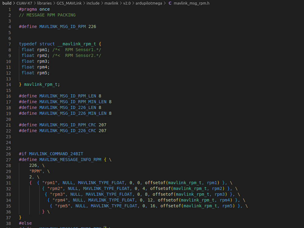
as well as all others to include rpm3 , rpm4, rpm5 but have no luck in making it show in GCS
mavlink inspector :
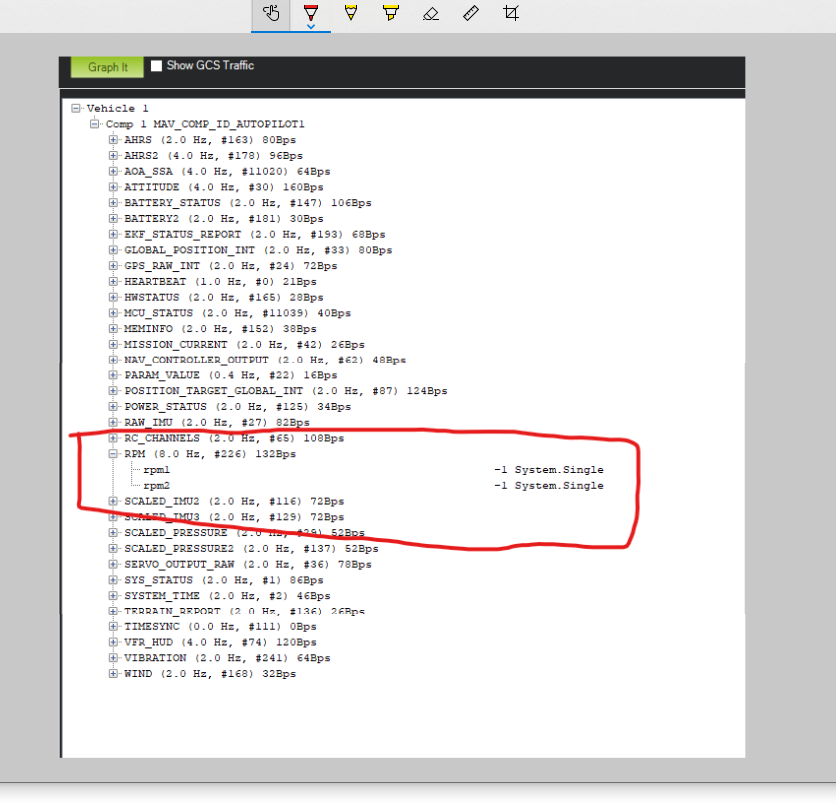
gcs :

We only support two instances of RPM in ArduPilot (esc telemetry is a different thing). So you would have to add more instances of the Rpm class to your build and then do the modification of the mavlink telemetry packets to add those new instances to the message. Just changing the define you have found will not work.
sorry i forgot to mention that i have added the instance, so that param and logging works for all 5 rpm sensors but not in the GCS side, i have also changed the send rpm but have no luck
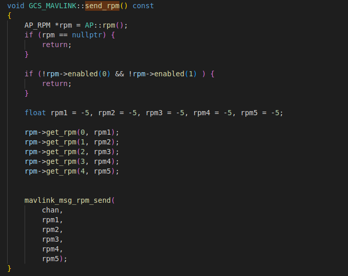
regarding the mavlink telemetry packets do you know how can i change them to enable 5 rpm sensors?
I am having a little trouble with RPM setup and hoping to get some help in this thread. Once it’s resolved I will summarize the solution so that it helps others later.
This is a cross-post from the ArduPilot Discord #copter_help channel - I’m not sure where everyone’s haning out these days… ![]()
My RPM setup for ICE RSC Internal governor is
always displaying RPM1: -1 and RPM2: -1 in Mission Planner (Cube Orange ADS-B Carrier)
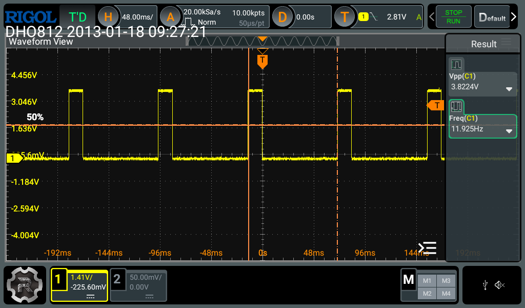
I think I have all params configured properly (below). I’m sending a waveform confirmed by my scope to have a valid frequency (12Hz/720RPM) and Vpp of almost 4V. See scope screen shot.
The waveform indicates the volage is low until the magnet approaches the sensor, then is briefly high.
Q: Should it be the other way? High, then Low when the magnet passes?
Q: Should the Vpp be closer to 5V? I was worried the Cube Orange might be limited to 3V3?
Here’s related config vars:
(allow pin 55 - Aux 6 to be GPIO)
SERVO13_FUNCTION -1
SERVO14_FUNCTION -1
(setup RPM1)
RPM1_TYPE 2 GPIO
RPM1_PIN 55 Aux 6 pin
RPM1_SCALING 1 one magnet
RPM1_MAX 100000 default
RPM1_MIN 10 default
RPM1_MIN_QUAL .5 default
SERVO1_FUNCTION 33 Motor1 (headL)
SERVO2_FUNCTION 34 Motor2 (headR)
SERVO3_FUNCTION 35 Motor3(headA)
SERVO4_FUNCTION 36 Motor4 (tail)
SERVO8_FUNCTION 31 HeliRSC
(edit) My sensor works well with the Arduino sketch provided in the RPM Measurement docs in the Ardupilot Copter pages.
Any help appreciated.
Hi Fred.
i killed a pixhawk board with 4.5-5V. Maybe better go for 3.3V voltage. ![]()
Cube Orange inputs are definitely limited to 3.3v. Some flight controllers have an ADC input for 6v but that is specifically marked as such.
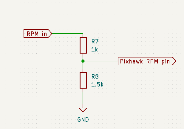
Use a simple voltage divider:
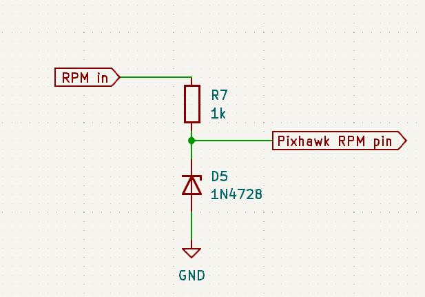
Or if you are worried about spikes and noise on the RPM signal use a resistor and zener:
Thanks for the tip. I added a voltage divider and tried on another Cube Orange (new) with a Spektrum SPM9560 rpm sensor. I see no indication of rpm on the Mission Planner Status tab for rpm1 and rpm2. both show -1. There must be a setting I’m missing. I’ve double checked these params, and I’m using AUX6 on a CubePilot CubeOrange+ at this time. Thanks again.
SERVO13_FUNCTION -1
SERVO14_FUNCTION -1
(setup RPM1)
RPM1_TYPE 2 GPIO
RPM1_PIN 55 Aux 6 pin
RPM1_SCALING 1 one magnet
RPM1_MAX 100000 default
RPM1_MIN 10 default
RPM1_MIN_QUAL .5 default
Try here: https://discuss.px4.io/