Well provided that the RPM sensor is connected to the same aux port as you had on the cube then the params (RPM_, BRD_PWM_COUNT, and RELAY_) will be exactly the same between both boards. So I would do a param compare between your two setups to double check (but from your screen grab it looks as though your params are correct). So if the if firmware is the same (and from the ap build server) and the params are the same between the two boards it suggests to me it is a wiring issue.
In your image, you have written sensor PWM input. What type of sensor are you trying to use? Is it a hall effect sensor?
I’m using an optical laser based sensor, yes everything is fine with the sensor input and the readings (from CubeBlack) cross validated with a tachometer as well, just getting it to work with Pixhawk 4 was the idea, so trying that in the free time.
Ok wiring, should the grounding given to the sensor and the PDB be the same? I have 2 different grounds, is that causing this?
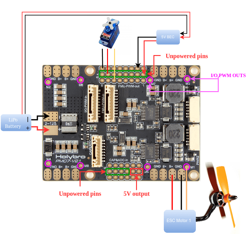
I have not got a Pixhawk 4 to test locally, but i think it might be a wiring issue. Have you checked that you are geting 5V on the servo rail you are connected to? The reason I ask is because this pin out suggests that the servo rail you are on does not have 5V and need to be powered from a seperate BEC
Also, I am just curious. Why are you trying to get it to work on a pixhawk 4 if you have a cube? Cubes are far better hardware IMHO.
Alright, I will check everything from scratch
In my lab they use Pixhawk 4 on most of the quadcopters, so they were like just test it out and see if it works out, but yeah I would agree to your point, anyways thank you so much, after I finish the project I will make a repo to help others as well, i dont see a lot of people using optical sensors so lets see.
Complementary answer:
Yes, the RPM library is the same for a CubeBlack as for a Pixhawk4, just change the command for when you compile the firmware in each case and the pin number.
I can’t set up the data rate, but from my experience, I receive data every 25 ms.
Hi all,
I have added two extra instances of rpm to the default 2 instances (rpm1,rpm2,rpm3,rpm4)
I want to see this as a MAVLink frame in my tlog file.
I have cloned Copter 4.0. branch
Does anybody know which file to modify in this so that I can make these changes and get my rpm data as MAVLink message frame?
Any help would be nice.
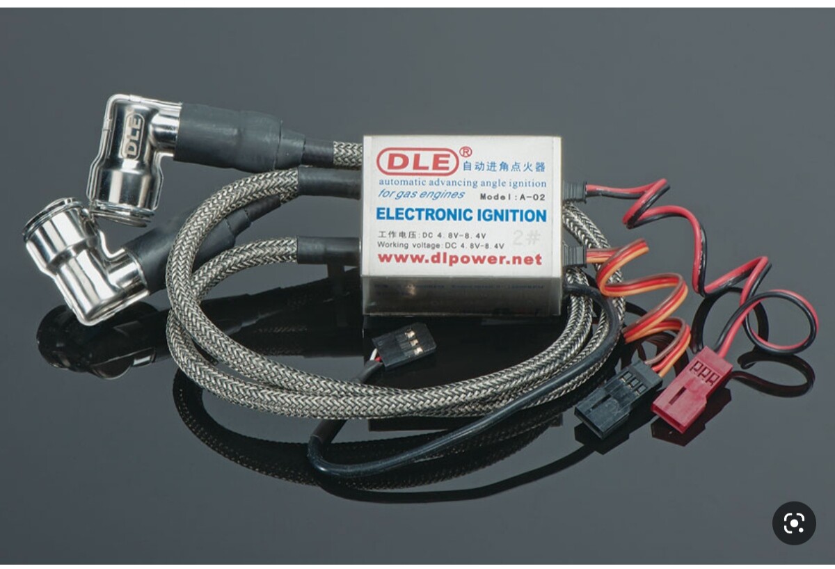
@IAMMATT Hi, may be you can help me with my problem with rpm measurement, i have DLE 60 and get tachometr data from CDI, i testing it with arduino sketch and all good, now i connect it to PWM13 on my CUAV x7+, and set SERVO13_FUNCTION to -1, RPM_TYPE2 set to 2 (and tested 1 from wiki), RPM2_PIN is 62 , but rpm in status -1,
and i am using optical kill-switch (no power to cdi before arming)
brookman(takeoff,rpm,gimbal).param (21.4 KB)
today all working)))thank you)
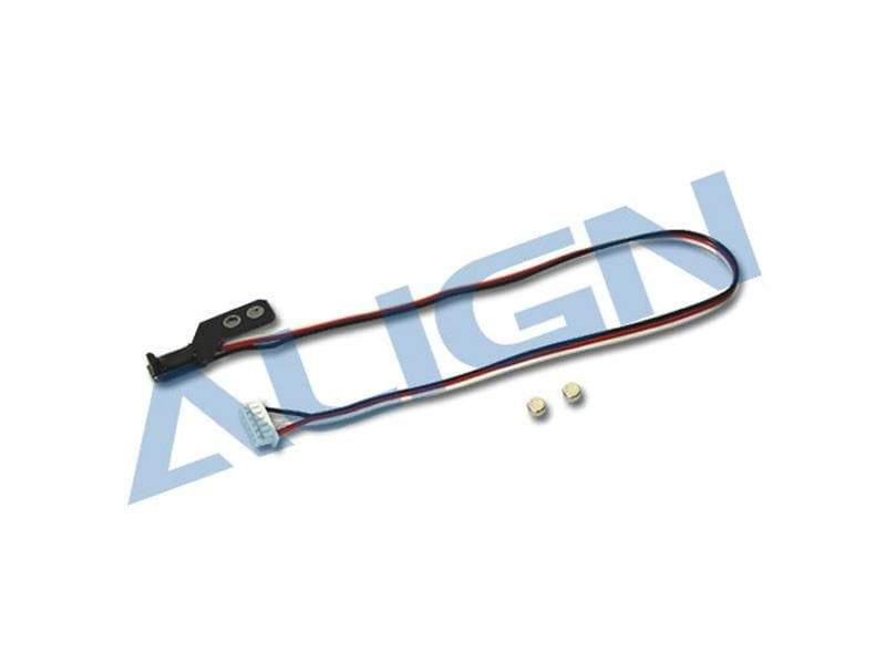
hi matt i am using pixhawk1 and i want to use the rpm sensor shown in the picture how can i connect it please help me
Hi Matt,
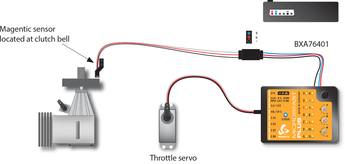
I look at the photo for Align BeastX RPM Sensor (SKU: HEGBP001T) and the upper right corner of the photo for the BeastX Governor RPM Sensor Connection (the socket for the Align BeastX RPM sensor’s 6-pin plug), I think the Red wire is for Vcc, Black wire is for Gnd, The White Wire is for Signal, there is no need to swap the wires in this Align BeastX RPM sensor. The one that need to swap the wires is another version of Align RPM sensor designed for Align governor RCE-G600 (SKU: HE50H22) with 3-pin plug. Here.
Can you confirm this and correct this Wiki?
I read from other thread and heard about the problems of connecting the RPM sensor to the AUX port of Pixhawk (set as GPIO) with servo rail operated at higher than 5V. Have the problems resolved? If not, what’s the solution if I definitely need to use higher voltage on servo rail and connect the RPM sensor to AUX port?
Also, could you please tell me which Arduino board I should buy to run the Arduino Sketch as I have never used any Arduino before, and need to know which one is cheap and capable. How do you display the Arduino messages at computer screen or type commands, set parameters in Arduino?
Thanks.
You can use another source of 5V instead of servi rail or keep servo rail at 5V and power the servos externally.
Thank you, the problem has been resolved. The error was in the feed
hello…
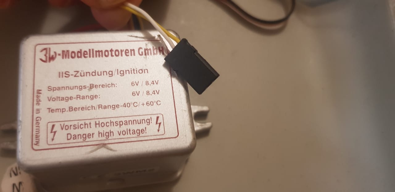
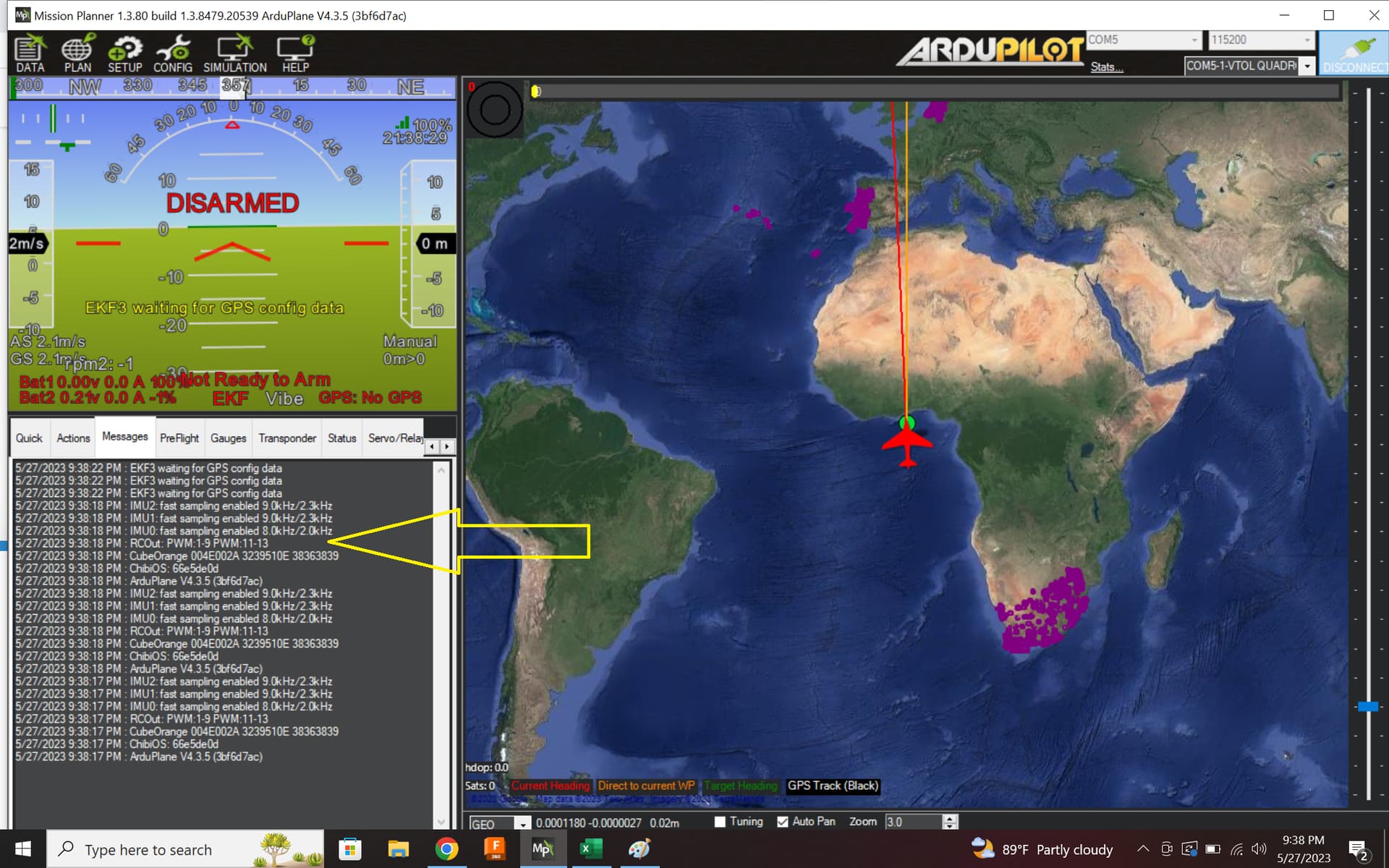
after writing across the ardupilot discuss i finally found this page and hope i can get some help here as this knowledge share corresponds to the the problem i have in hand… i have a orange cube and running ardu 4.3.5 with a 30cc 3W gasser engine (not sure which is the signal wire and which is power so have tried swapping both but no joy till now… have written the the manufacturer about this already … i am not able to set up the rpm sensor and the HUD display only shows RMP2: -1
below is the sequence
A) Aux out pin 6 from the orange cube is SERVO 14… hence have set
servo14_function = -1 (for GPIO)
C) rpm2_type = 2 (for GPIO)
D) rpm2_pin = 55 (for AUX6)
i have powered up the orange cube but i still get to see RPM2: -1
anyone can show how its done as i have tried to ask in quite a few places without any answer… have attached the parameter file too for references
much appreciated your help
regards
may28th 2023.param (22.2 KB)
1 Like
Hi @sujju,
A couple of things:
- Do you have an Arduino (script here: ArduinoHallEffectDebug.ino) or an Oscilloscope, or even a multi-meter, available to you. It is really worth figuring out the orientation of the pins from the hall effect sensor. Do not trust the the colour of the wires or the position that they are in on the servo plug. I have seen every combination, including black wire = signal …(which is incredibly frustrating for the user!).
- Why are you starting with RPM2? I can see that you have not assigned anything to RPM1_TYPE. I do not believe this will cause any issues but I recommend that you move to RPM1 for a more conventional setup.
- Unfortunately, because of the way that the PWM timers work you cannot get each channel as an input or output quite as simply as it may seem. Some channels are “ganged together” on the same timer.
Because 13 is being marked as PWM and is on the same timer as 14, it actually means you cannot use 14 as GPIO. In other words, you have to have both 13 and 14 as GPIO or not. Try setting SERVO13_FUNCTION to GPIO as well.
Also, how are you testing this? Be aware that if your measured RPM is less than RPM*_MIN then the value returned to the ground station will be -1. So, based on your params you need at least 10 RPM to see a none -1 value
Hi matt… thanks a ton for this … was quite desperate for a solution… unfortunately i don’t have a Arduino but can be bought from a local store here … will to set it up and will inform ( i do have a multimeter but iam not great at electronics hence don’t know how to figure the orientation of the wires)… and will also try the other suggestion now that you have stated… much appreciated mate for this…
regards
understood… then i will have to start the engine to get the rpm ( i thought if i set it right the value will show as 0 and not -1…which is clearly not)…