RPM Sensor Wiki - Knowledge Share

Hi Rodrigo. I’m glad you got it working :+1:

Gentlemen,

@tridge @bnsgeyer @IAMMATT @ChrisOlson

I am having a issue with an RPM sensor, ArduCopter v4.0 + and warning message “RPM: failed to attach to Pin255".

The RPM sensor is Align Beast X (One of the ones Chris recommends) with Vcc and GND swapped and pull up 360ohm resistor between Vcc and signal. (As per this RPM Sensor Wiki thread. RPM Sensor Wiki - Knowledge Share). I have had it on the oscilloscope and works fine and it outputs 0 to 5v steps similar to this picture with a passing magnet.
image

Autopilot is : Cube Black V4.0.6
BRD_PWM_COUNT = 4
Relay_Pin = -1
RPM_Max = 10000
RPM_Min = 10
PRM_Min_Qual = 0.5
RPM_Pin = 55 (Sensor plugged into Aux 6)
RPM_Scaling= 0.5
RPM_Type = 2

RPM displays “-1” when the magnets are stationary but was expecting “0” to be displayed.

I mention the problem in Bill’s TradHeli Autotune thread but it’s not the right place to ask and thought it best to ask the question in here.

As you can see at the bottom of the screen grab below. I can get a RPM reading of 1338 with the cordless drill spinning two magnets. The warning message “RPM: failed to attach to Pin255” still appears though. I did try a few different versions of firmware on the same airframe to try and narrow down what might be causing it.

ArduCopter V3.6.8-L1Nav, RPM worked fine and did not display the warning message. :+1:

Helipilot v21-beta-cubeBlack, RPM worked fine but got the warning msg “RPM: failed to attach to Pin255”

ArduCopter V4.0.6-ATNH-rc1, RPM worked fine but also got the warning message “RPM: failed to attach to Pin255” (see below and log file.)

https://drive.google.com/file/d/1woi2qMQ5JRahXcNtGdXfwZVsjnE8S4b9/view?usp=sharing

It looks like something in ArduCopter V4.0 is causing it. After Googling it, It would seem Matt @IAMMATT had a similar problem with SITL.

Do you have any idea what might be causing this warning message?

Thanks and regards,
Steve

Update to my post above:

Thanks to Bill, the warning message “RPM: failed to attach to Pin255" is fixed now. After looking at my log file, he found that I had RPM2_TYPE set to 2 and RPM2_PIN set to -1 which was causing the warning. I wasn’t using RPM2 so setting it back to RPM2_TYPE to 0 fixed the issue.

Hello to everyone¡¡ I am trying to active 4 RPM sensors, in order to read angular velocity of each motor of a quadcopter. In the Full List Parameters I can only configure two of them. I modified the firmware code adding the lines for RPM3_PIN and RPM4_PIN and changed the number of maximum RPM measurements to 4. I loaded the code as : Load custom firmware using Mission Planner. But the New Parameters added do not appear. I am using EMF sensors, Hobbywing RPM sensors. Actually, I can see the the signal of two of these sensors. Does anyone know what could be wrong? A

Arpm4 ny tip will be really appreciated. Thank you.

Hi Giovanna.
Have you instantiated two more instances of Rpm sensor as well as adding the new params?

Also, it looks as though you are overwritting the variables of the second instance or Rpm sensor. E. G. _scaling[1] in 3_SCALING should be _scaling[2] (you will need to increase the size of the arrays that store these too)

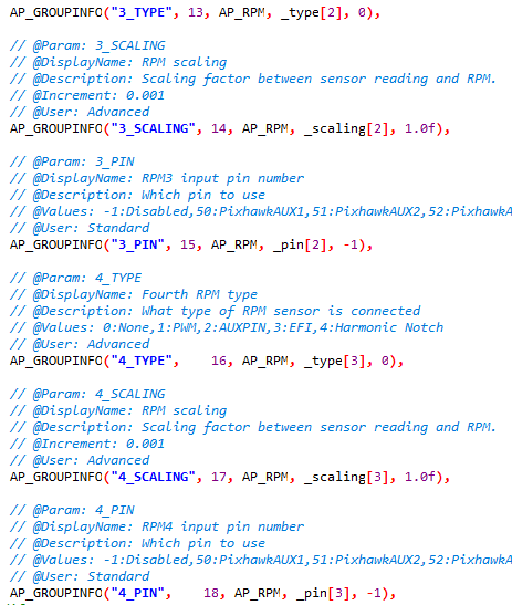
Hi Matt¡ Thank you for answering. Yes. I added two more instances and new params.

rpm4


RPM_enable
RPM_size
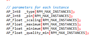
I changed the code as you suggested. But where can I change the size of the arrays? As I understand the size of the arrays depends on the variable RPM_MAX_ INSTANCES in the AP_RPM.h header file.
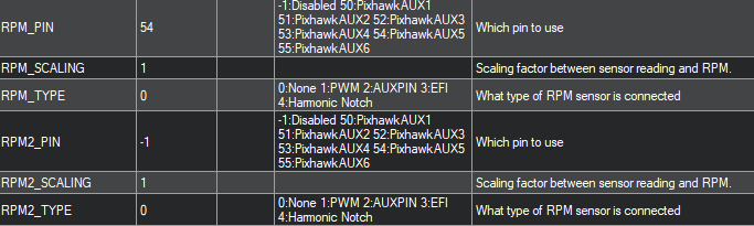
I still can not see these new parameters in Mission Planner. Please help ¡¡¡

OK, so the param variables are being resized :+1:

Send me a link to your branch and I can have a look for you.

Matt¡ Thank you for doing this. This is the link of my branch. I really appreciate it. :grinning: :pray:

I have found the issue and created a PR against your branch. In short, it wasn’t anything that you were doing wrong. It was just a bit of a confusing situuation with the way that the param variables are created.

Dear Matt:

Thank you very much for taking the time to review this and for your patience. You are saving my life. I incorporated all the changes from your kindly contribution on the Fix parameter memory allocation you shared.
I made a clean build of the project with:
./waf configure --board fmuv3
./waf copter

Then I flash the firmware into the physical board Pixhawk, by selecting Load custom firmware and arducopter.apj in Mission Planner. After a successful load, I press Connect -> CONFIG and go to the Full Parameter List.
I hope to see the new parameters RPM3_PIN and RPM4_PIN and their corresponding RPM3_SCALING, RPM3_TYPE and RPM4_SCALING, RPM4_TYPE to be able to set up them. But these do not appear in MP. The same thing happens to you when you try to load the modified firmware with these changes in MP?
Do you think I should do an additional step to see these new updated parameters in MP?
I’m sorry, I don’t know if the solution of this would be related with chosing the wrong board in the compiling process, or do I have to request a pull request in the master branch so that MP allows me to see these changes or do I have to do an additional step in which these variables can be seen in MP? Please, any insights are greatly appreciated it.

Hi Giovanna,
This is getting outside of the RPM specific stuff now. So I will PM you to assist, so as to keep this thread specific to RPM senors.

1 Like

Dear Matt, we are trying to get the RPM. We have a standard outboard motor installed. The tachometer signal comes out from the motor, we send a 5 volt signal to the HEX Pixhawk CUBE BLACK 6 aux pin 55 through the optocoupler. The ardopilot does not show RPM1.
temp.param (14.8 KB)
Can you help us in any way?
Link to our project.

Hi Alexander,
I notice in your param file that relay_pin and relay_pin2 are set to 54 and 55 respectively. I assume you are not using relay. Try setting these to -1. That may be the cause of your issue.

What does the signal from the tachometer look like? Is it 0 to 5 V plus signal? Like that shown in the example on the wiki?

Hey, whats the maximum number of RPM Sensors (I would need 4/6) that can be accomodated on a Cube Black, looks like you did 4, and also is it supported by PX4 Firmware yet or just Ardupilot? Thanks in advance!

Hello!!
Yes that’s true, I was able to get 4 working with Matt’s @IAMMATT help. I think the maximum number of RPM sensors you can accommodate is 6, as it depends on the number of auxiliary pins on the Cube Black that you can program as GPIO. I think you will have no problem implementing them. Regards.

Thank you so much, I will test it out.

Hey, a couple of doubts, I feel the others might be benefitted out of it as well:

  1. Instead of the AUX Pins on the Cube Black, can we connect the sensor to FMU-PWM-OUT or IO-PWM-OUT of Pixhawk4 and get the RPM values directly? and if so, does the AP.RPM Library for Pixhawk4 does the same calculations like on the AP.RPM library in the Cube Black?
  2. What was the data rate that you used of the 4 sensors that you had implemented?
    Would be great if you answered these questions, thanks in advance!

Only sensors connected to the fmu can be used. There is a buffer between the fmu and iomcu that means we can’t read from the iomcu pins.

Regarding the rest of your questions, I would recommend looking over the wiki page on Rpm sensors for how Rpm Aux pin sensors work:
https://ardupilot.org/copter/docs/common-rpm.html

Hall effect Rpm sensors work exactly the same for every board and they do not have a data rate. We calculate the Rpm based on the time passed and number of falling edges in the voltage signal.

This is my setup and parameters, im testing out one sensor and it fails to read rpm.
Same thing works seamlessly on Cube Black and Arducopter v 4.0.6
Now i have flashed Arducopter v4.0.6 for Pixhawk4

Any help would be appreciated!

Is this causing any problem?

Relay is off so that’s good.

Also check that you have set BRD_PWM_COUNT to 4 or or less.