@GRS26, yes, that’s right. It seems that when using GPS-for-yaw, the best result should come from using the 1st GPS for position and velocity and the 2nd GPS for yaw. If GPS-for-yaw isn’t being used though this statement isn’t relevant though.
But does it have to be this way? Until beta5 I was connecting only the rover gps to the fc, the moving base one only connect to the other module. Can I still use like that?
Sorry, I misunderstood your question so I answered incorrectly…
Yes, I think that should be fine… I’ve never actually used GPS-for-yaw myself but I think the data from both GPSs is still reaching the autopilot even if only one is physically connected to the autopilot.
Randy, I certainly could be wrong, also, but I do not think that the position information from both GPSes will come through if only one is connected.
But still, to @GRS26 question, if only one is connected (and if I am right that this one’s position is the only one that it reports) , that would certainly be the one that Ardupilot would use for position since that is the only GPS it would know about. So, @GRS26 should get what he wants, I think.
1 Like
correct. You only get position data from the GPS modules that are directly connected.
yes, it should work, but only connecting the rover will lead to lower position and velocity accuracy and some nasty failure modes.
The position and velocity on the rover is always worse than the position/velocity on the base because it is equal to the base plus an error that comes from the RTK process.
When the rover has a good fix type 6 RTK lock then the position/velocity on the rover is ok (just a bit lagged from the base, and with only a few cm of additional error).
But when the rover loses its RTK lock on the base (eg. goes to fix type 5) then the position/velocity on the rover can become a lot worse than the position/velocity on the base. I’ve seen errors of several meters at times.
This is why for copter 4.1.0beta6 we’ve changed the setup to use the base GPS as the primary. It gives more reliable position and velocity. The EKF can cruise along without the yaw for quite a long time, but if the GPS gives it rubbish for the position and velocity then things can go badly wrong fast, especially when the GPS claims to have high accuracy (which it usually does when in fix type 5).
1 Like
Thanks for the clarification. I had seen, in the code (a couple of months ago), comments about switching to the Moving Base for position IF the rover lost type 6 RTK, which made sense for the reasons you cite. I can see where it makes more sense just to use the Moving Base all the time, as you are now doing.
With 4.1.0 beta5 the connection thru wifi to my pixracer with esp stops working, It can’t download the parameters anymore, both in mp and qcg.
Reverting to 4.0.0 fixes the problem.
Just another data point. Rover 4.2.0-Dev PixRacer does work fine with WiFi on QGC/IOS and MP/Windows.
Txs for the report. The esp wifi uses a normal serial connection so it should just be a matter or parameter settings but I could be wrong of course. Could you download parameters (using a USB) when the vehicle is running each versions and then we can compare them and see if there are any differences.
I think I may have discovered an issue with INS/GPS frame position offsets.
Brief background: I recognized that I never properly set the GPS_POS_X and INS_POS_X parameters on my Rover mower. I set the GPS Y axis offsets for use with GPS yaw, but the fore/aft offsets remained at zero, which probably explains why I can’t completely eliminate oscillation in the navigation controller. But when I set those per the documentation, my previously excellent pivot turns became odd.
The GPS antennas are 0.366m left and right of center, 0.07m aft of the rear axle, about which the mower pivots. The Cube Orange is 0.27m forward of the rear axle, centered left/right. I set the following per the documentation, expecting perfect results:
GPS_POS1_X=-0.07
GPS_POS2_X=-0.07
INS_POS1_X=0.27
INS_POS2_X=0.27
INS_POS3_X=0.27
What I got was this (about a 1 foot radius circle on the position track, despite the mower physically pivoting almost perfectly in place via a manual mode pivot):
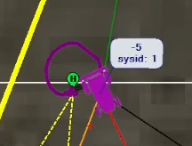
After more time messing with position offsets than I care to admit, I discovered that if I lied to the FC and told it that the GPS antennas were exactly as far aft of the INS position as they actually are aft of the physical centroid (GPS_POS*_X=0.20), I could achieve a much cleaner pivot turn:
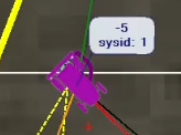
With those physically strange settings, the pivots in all modes were nearly perfect, where with the settings per the actual measured positions, pivots in auto/acro/steering modes were a bit odd (not purely pivoting in place), and the resulting track on screen showed some radius or diagonal between the start and end of the turn.
However, navigation oscillation was worse if I used the settings that resulted in better pivot turns. On the contrary, if I set the measured/correct ones, I could nearly eliminate navigation oscillation, with the penalty of slightly poor pivot behavior.
I hope I’m explaining this well, since it’s a confusing concept, and I may well have a misconception regarding expected behavior. If it helps, I posted a YouTube video on the subject. Skip to 3:02 if you don’t want a repeat of the background discussion I posted here.
As always, I’m happy to provide .bin logs for any set of parameters tested. I’d include them now, but the logs I have at hand are extremely large due to the length of time I tested and tuned.
Based on a discussion with @ktrussell, it appears this may be unique to 4.1.0, as his observations with the present stable release seem to coincide with pivot behavior expectation, where my observations over the past 2 days using 4.1.0-beta releases do not. Unfortunately, I don’t have a yaw source accurate enough to successfully revert to 4.0.9, so I can’t confirm that suspicion. I do know that the possible issue is present from 4.1.0-beta1 forward.
2 Likes
I might ask @tridge and/or @priseborough to chime in here but I think it must be best to get the stable position during pivots and if this leads to oscillations in navigation then it should be possible to re-tune either NAVL1 param sor the turn rate controller and restore performance to what it was (or better).
So the key point I think is whether the GPS_POSn_X/Y/Z positions are relative to the autopilot’s IMU or relative to the middle of the rear-axle (aka COG in the docs). The docs say this:
In practice the distance to the sensor can be measured from the center of the autopilot unless the autopilot itself is placed a significant distance from the vehicle’s center of gravity in which case the IMU position offsets can be specified and then the other sensor’s position offsets can be specified from the vehicle’s center of gravity.
If we have an issue in the code I think it could be here in NavEKF3_core::CorrectGPSForAntennaOffset and this code does seem to use both the GPS offset and the IMU offset. TBH I would have thought that we shouldn’t have the IMU offset in the calc but I think I better let Tridge and Paul weigh in.
Txs for the report.
2 Likes
Randy, you and I interpret that line of code the same way - it makes perfect sense to explain the behavior I’m seeing.
const Vector3F posOffsetBody = dal.gps().get_antenna_offset(gps_data.sensor_idx).toftype() - accelPosOffset;
Assuming the first term’s X component is my “cheater” offset of 0.2, and accelPosOffset.X = 0.27, then:
0.2 - 0.27 = -0.07 …or… the exact physical position of my GPS on the mower.
I’ve been meaning to set up a dev environment for a while now, and this is the perfect case for me to give it a shot. Thank you!
Also looking forward to further replies by the EKF masters - I definitely don’t want to induce unwanted behavior or error here.
As for tuning for perfect pivot positioning vs proper accelerometer offset, I agree with your assertion, in theory, that one should be able to tune the oscillation out, but I tried for a LONG time to do just that, and I settled on accepting the imperfect pivot turns as the best tune for my use case.
2 Likes
@rmackay, @tridge, @priseborough
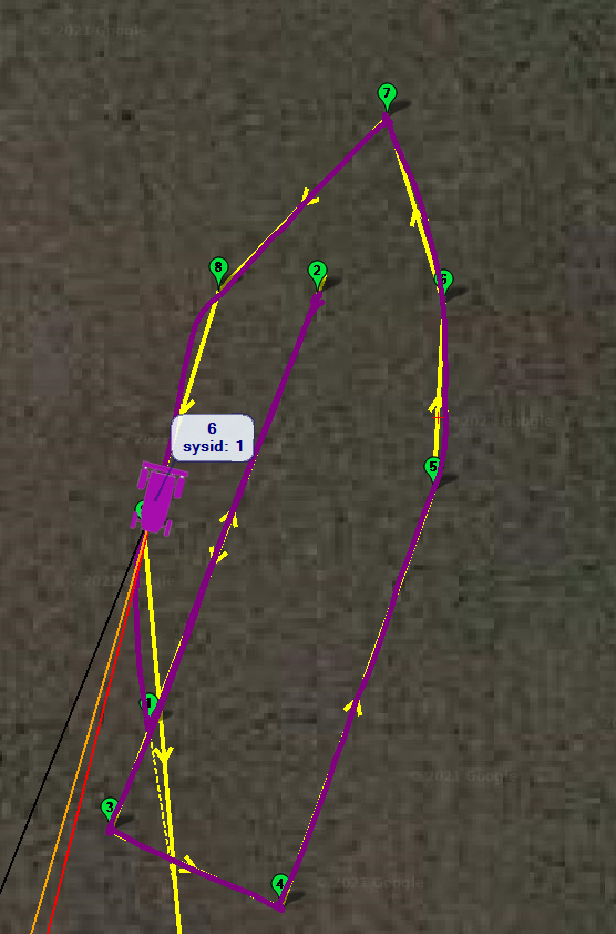
I set a build environment up today and made that singular change to which Randy alluded. It completely fixed the strange behavior with respect to frame position offsets. Unless it creates unwanted side effects, line 330 of NavEKF3_core::CorrectGPSForAntennaOffset should read:
const Vector3F posOffsetBody = dal.gps().get_antenna_offset(gps_data.sensor_idx).toftype();
The resulting tune (with the frame position offsets set per their measured/correct positions) made this excellent auto mission path:
Unrelated to this issue:
I first built the latest 4.2.0-dev master with ONLY this line 330 change incorporated, and I had a dangerous outcome. When I powered the mower, all of the relays were triggered opposite their previously default positions, simultaneously engaging the starter solenoid, PTO clutch, and exterior lights. I didn’t investigate too much because Randy mentioned it’s likely better to continue testing the beta releases for now, but I didn’t notice any significant parameter changes that would explain the behavior. A switch to the Rover-4.1 branch had the relays all behaving as expected again.
2 Likes
Thanks for testing this, I’ll raise a PR shortly with the change and we can see what some of the other devs think (in particular Paul and Tridge).
We’ve recently changed some things to do with relays including removing the BRD_PWM_COUNT parameter. Perhaps something has gone wrong with that. I’ll ping @tridge.
2 Likes
Thanks, Randy, that was some quick work on your part to discover the likely culprit in the EKF3 code.
As for the 4.2.0 relay changes - it may not be that things have gone wrong so much as there may be some new defaults that are opposite the settings I presently have. Probably worth a word of caution if the parameters/settings are going to change significantly.
Here’s the PR where some of the discussion will likely happen re the offsets.
I chatted with Tridge about the relay issue and we think, as you suspect, that it is the change in the defaults. In 4.1 we default the top four (?) servo output channels to be GPIOs but in 4.2 we removed BRD_PWM_COUNT and somewhat accidentally changed the default so all servo outputs are now PWM. We think if you set SERVOx_FUNCTION = -1 (GPIO) for the relevant channels then you’ll be back to the old behaviour. I’m not sure if you’ve got the appetite to try that or not…
We are thinking of ways we can make this transition safer and I suspect we will end up doing a parameter conversion and/or changing defaults to that these SERVOx_FUNCTION values are set automatically as part of the upgrade.
1 Like
Perfectly happy to lend a hand if that code is ready for testing. I can power the Cube via USB to make parameter changes without triggering relays. Just caught me completely off guard when I used my usual power-on process and all of a sudden things were spinning and flashing!
1 Like
@rmackay9, I read the PR, in which you state that either the code should be changed or the documentation changed. @Yuri_Rage needs to weigh in here in case I have it wrong, but I thought that BEFORE Yuri modified the code, he set the position parameters in a way that assumed that the IMU offset was included in the calculations and he got great pivot turns, but then his normal tracking had bad oscillations, implying that there are other places in the code that do not include the offset. (See the text beginning between the screenshots in post 24 above: Rover-4.1.0-beta6 released for beta testing! - ArduRover / Rover 4.1 - ArduPilot Discourse). If I am right, then a code fix would be required, not just a doc change.
I may be completely wrong. Yuri?
2 Likes
I strongly believe that the code change is necessary and appropriate.
First, to tackle the “easy way out” of changing the documentation alone: the way the EKF3 posOffsetBody is calculated, the documentation would become quite confusing in a hurry. While you can simply measure the IMU position with respect to the vehicle centroid and enter those values into the INS_POS* parameters directly as measured, you cannot for the GPS antennas. Nor can you simply measure the distance between the IMU and antennas - the subtraction won’t work. To properly set the GPS antenna position offset with the code as written, you need to make reference measurements to the vehicle centroid and then subtract those values from the IMU offsets to achieve what I believe to be the correct GPS_POS* parameters. I think I even confused myself just trying to write that.
As such, I agree with Randy’s comment in the PR discussion - it makes no sense to re-accomplish all sensor position offsets if the flight controller is re-mounted in another position on the vehicle. The reference point should always be the vehicle centroid, and the firmware should account for all offsets relative to that.
I think body position offset error becomes particularly evident during rover pivot turns, where the degrees of freedom are limited, the EKF must calculate position faster than a sensor (GPS) can bias it toward reality, and the vehicle has no ability to translate laterally (on the Y axis) in space, so any error results in undesirable course “corrections” upon exiting even the most physically perfect of pivot turns.
After reading some of the code, it’s still unclear to me why I had to fight so hard to tune the oscillation out of the nav controller with the GPS_POS* values referenced to the IMU, since the result should’ve been proper relative GPS position. I suspect that somewhere else in the control/performance loop(s), the GPS offset may be referenced to the centroid rather than to the IMU. Observed evidence after making the change to the code today strongly suggests that it results in desired behavior and also matches existing documentation.
1 Like
Flight vehicles ‘pivot’ about the centre of mass, ground vehicle with steered wheels rotate about the non steered axle. If the all the *_POS_X,Y,X params are set up relative to the non-steered axle, then a yaw rate won’t produce a cross-track velocity. This should make the L1 trajectory controller easier to tune. The c.g. position is largely irrelevant for this application.
2 Likes