Rover-4.0.0 released!

Hi. Thanks for your answer.

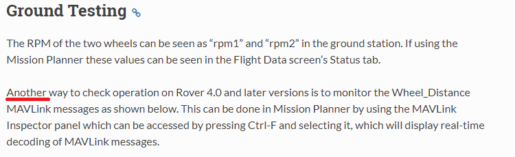
Unless I am still seeing an old version of “Ground testing” here, ‘another’ would mean that in v4.0 on you could do the test both ways. v3.5.2 permitted do an easier test of the encoder signals (in fact, rpm1 and rpm2 change even moving the motors by hand). MAVlink distances are not very informative.

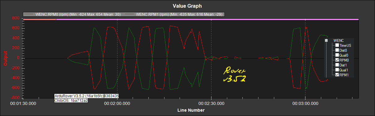
For the motors I use, CPR is not clear, so I wanted to adjust it with a tachometer. So I installed v3.5.2 in a spare pixhawk, and connected there the encoders. With rpm1 and rpm2 I could get values for WENC_CPR and WENC2_CPR (rpm1 and rpm2 as appears in tachometer).

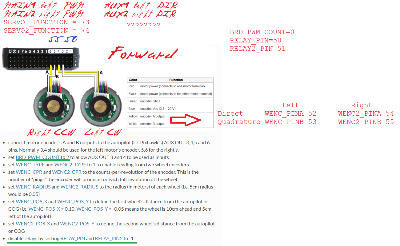
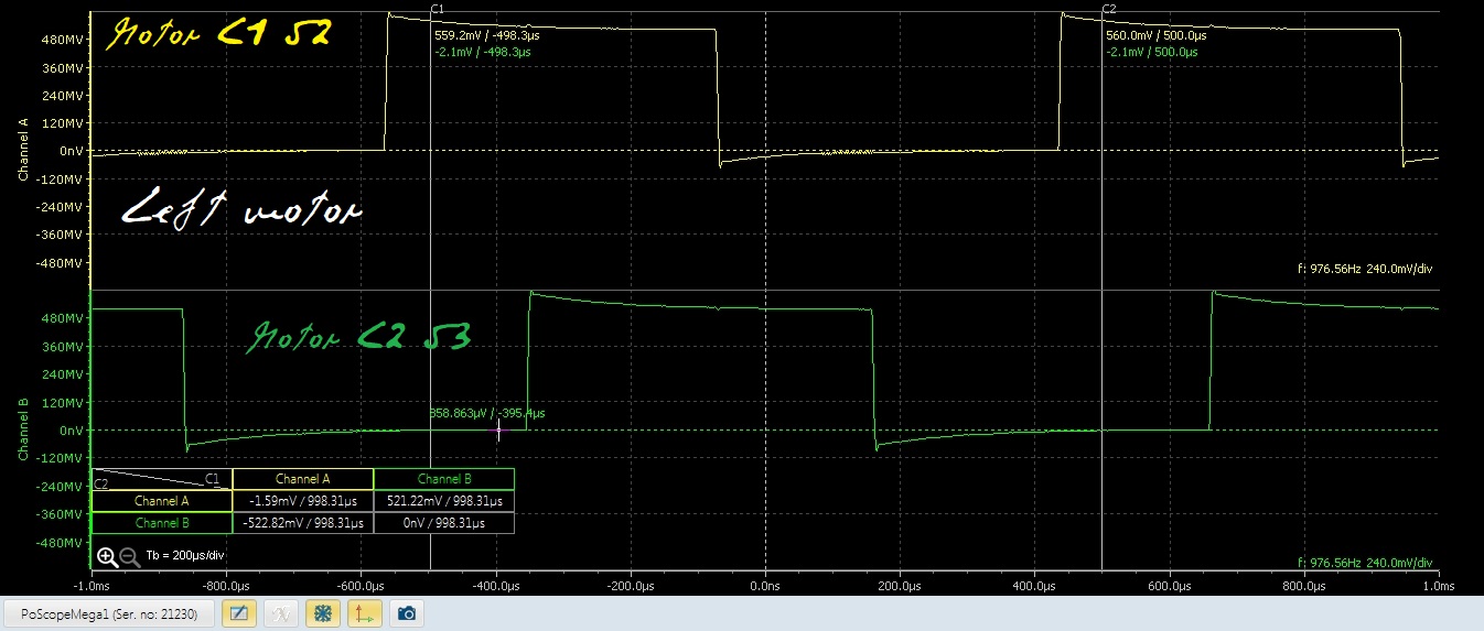
But there is not much information about the connection of the encoder signals. Note that with two motors (left 1 and right 2) there is an asymmetry since for forward movement the left motor (seen from left) turns CCW and the right one (seen from the right) turns CW.

Here appears:
…for rovers with skid steering, “Test motor C” should cause the left wheel to turn forward. “Test motor D” should cause the right wheel to turn forward.
but that doesn’t give indication about encoder signals.

This motors test works for me, and in adition with the vehicle seized, leaning it forward the wheels moves forward and leaning it backwards the wheels move backwards.

For considering the left and right motors asymmetry mentioned above I use:
WENC_PINA,53
WENC_PINB,52
WENC2_PINA,54
WENC2_PINB,55
with:
52 (AUX3) going to left motor C1,
53 (AUX4) going to left motor C2,
54 (AUX5) going to right motor C1,
55 (AUX6) going to right motor C2,
(C1 and C2 are the labels on motor encoder signals)
but I cannot find information about if this is correct.

For directions:
MOT_PWM_TYPE,3 (BrushedWithRelay)
RELAY_PIN,50 (AUX1, left motor)
RELAY_PIN2,51 (AUX2, right motor)
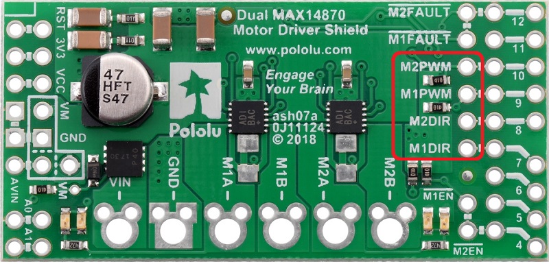
For motors PWM’s:
SERVO1_FUNCTION,73 (left)
SERVO2_FUNCTION,74 (right)
better than what appears here (SERVO3_FUNCTION, 74), since in this way connectors are all together and tighter.

But the vehicle is not yet stable even with no RC inputs: it moves back and forward and falls.

This is a log with the vehicle armed (transmitter off (no RC)), first seized by hand and leaned back and forth, and then released on the floor partially (if released completely it goes away and falls: it is unstable):


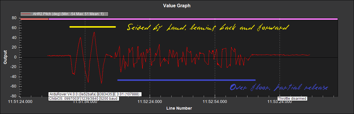
This happens even with a small battery, placed as low as possible.

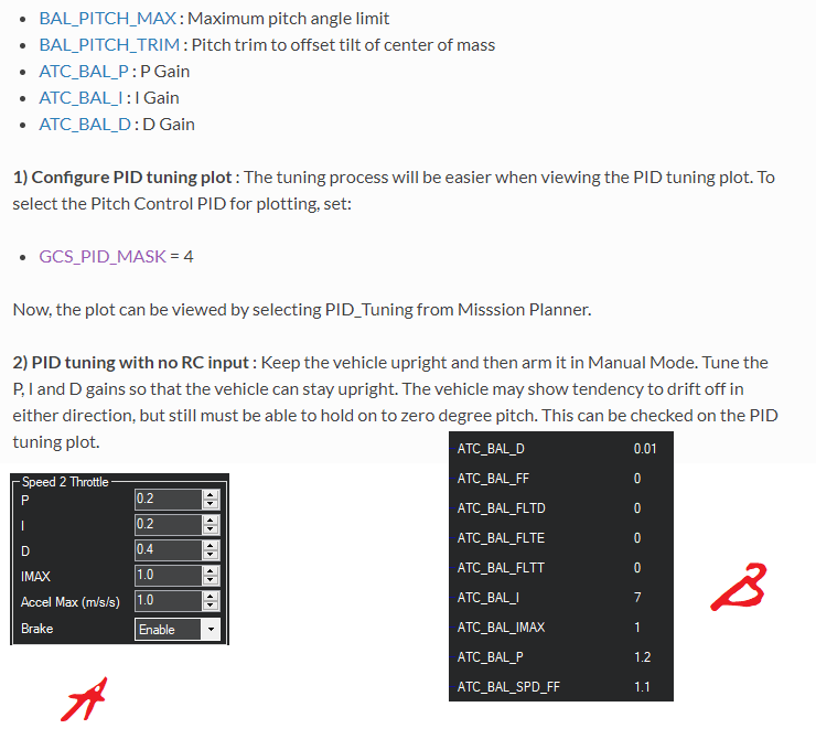
Varying PID parameters:
MP_basictuning
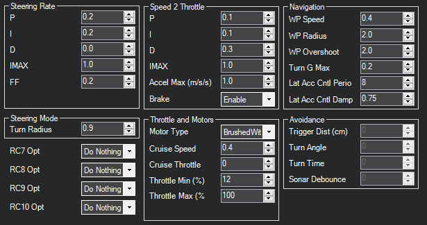
doesn’t change too much this unstable behaviour, so I suppose I have some parameter completely wrong. What can happen?

BTW1
GPS: u-blox 1 saving config
EKF3 IMU0 started relative aiding
u-blox 1 HW: 00080000 SW: ROM CORE 3.01 (107888)
fmuv3 004D0032 3238510C 38383435
ChibiOS: 0997003f
ArduRover V4.0.0 (0e52bafa)

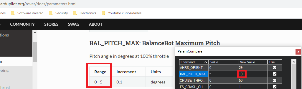
BTW2, it seems that default BAL_PITCH_MAX is 10, but in the rover full parameters list is at most 5:

Hi! For the balance bot, you will have to tune three sets of PIDs for balance, speed and turn rate. Only balance PID is used by the vehicle when it is in Manual or Hold mode. Wheel encoders are used mainly for speed and turn rate control and is not “necessary” to balance. So if your vehicle is unable to balance, you may have to retune the balance pids. It seems the balance PID parameters are not shown on the mission planner tuning tab, but these can be be accessed from the parameters tab. You can find more about balance bot tuning here: https://ardupilot.org/rover/docs/balance_bot-tuning.html#balance-bot-tuning
I would recommend that you read the balance bot wiki before you proceed(especially common issues):
https://ardupilot.org/rover/docs/balance_bot-home.html

1 Like

Hi. Thanks a lot for your answer.

From the tuning page:


I suppose that I must concentrate in B and not in A in MP.
What does the “PID tuning plot” refer to in MP?

About the “common issues”, my backslash is 1mm measured on the outer part of a 65mm diameter wheel (those used in 1/10 R/C asphalt racing). With a geared motor it is difficult to reduce it.

Some thoughts:

Thought 1:
I use a motor controller with DIR and PWM signals. It has been asked if a L298N Dual H-Bridge Motor Controller could be used which has signals for direct transistors bridge control. So inserting some TTL logic:
In1 = PWM1 * DIR1
In2 = PWM1 * /DIR1
In3 = PWM2 * DIR2
In4 = PWM2 * /DIR2
although perhaps it is better to use a microprocessor calculating above functions and aditionally braking the motor during some milliseconds when DIR1 or DIR2 changes.

Thought 2:
For no backslash perhaps the philosophy of crawlers with motor on wheel could be used, with motors as those used in gimbals. An rpm counter as those used in helicopter governors attached to the ESC’s could be used for velocity feedback.

Thought 3:
My plan is to emulate this on the balance bot using a RTK GPS (the track is narrow), in fact one of those on seen on the car roof.

Yes, B is the correct way.
Yeah, I don’t think anything can be done about the backlash if you’ve already bought the motors. But see that you have configured minimum throttle. You had also mentioned that you’ve moved the battery down. That may not always help, and in fact can also have a bad impact on the balancing performance.

To use the PID tuning plot in MP, this might help: https://ardupilot.org/rover/docs/rover-tuning-throttle-and-speed.html#desired-speed-to-throttle-pid-tuning. This is actually a tutorial for tuning speed control. For tuning balance, set GCS_PID_MASK to 4 instead of 2.

I’d say L298 is too much of a hastle, if you already have a motor driver with pwm, dir input. There are geared motors with encoders that are rated zero backlash. Still, I haven’t tried one of those yet. Auto missions should work fine with balance bots.

1 Like

Hi. Thanks again for your answer.

Varying parameters on B at least I see stability changes, but the vehicle is not still stable with no RC inputs: it moves back and forward and falls.

Motors used are 620rmp 12V that with 65mm diameter wheels should go up to 2m/s at full modulation.

I am using the Pololu 2519 dual motor controller (though it doesn’t provide much current):


which receives PWM and DIR signals ((M1/M2 signals to left/right motor)). The problem is that I cannot find documented where to connect the DIR signals and how to define its connection. So I did the following (pixhawk), supposing that RELAY_PIN would control the left motor direction an RELAY2_PIN would control the right motor direction:
DIR1 (left motor) to AUX1 (50)
DIR2 (right motor) to AUX2 (51)
BRD_PWM_COUNT=0 (all 6 AUX’s GPIOS, 2 outputs (1, 2) and 6 inputs (3, 4, 5, 6))
MOT_PWM_TYPE = 3 (brushed with relay)
RELAY_PIN=50
RELAY2_PIN=51
Other RELAY’s (3 to 6) -1 (GPIO inputs).

This doesn’t work: although DIR pins change, it seems as if different parts of the program fight with the DIR signals.

But if I adhere strictly to Wheel Encoders Connection and Setup (which says nothing about DIR connection for this type of control) with:
BRD_PWM_COUNT=2
RELAY_PIN and RELAY_PIN2 -1
motors direction doesn’t change. Is that definitely correct for this type of control?

I include here my interpretation of connections in that page, including other parameters. Please, indicate what I am interpreting the wrong way.

Green: doubts mentioned above.

From the encoder side, forward implies left motor CW (direct before quadrature), and right motor CCW (direct behind quadrature), or could be all the opposite.

What am I doing wrong?

On Copter v4 rpm1/rpm2 representation still works (and beautifully), since it is important for governors. See Helicopter Rotor Speed Governor.

For helicopter governors the rpm library is called internally from the main code and applied in the RSC object. It is not sent over MavLink.

Hi. I am years light from understanding the implications of this for Rover code. Surprisingly, in Rover release notes appears:
Rover 4.0.0-rc3 08-Nov-2019
Changes from 4.0.0-rc2

2) Bug Fixes:

c) BLHeli fix to RPM calcs and telemetry (aka 0x8000 error)

I experimented on the balanced bot with two pixhawks at the time (one over the other), one with v4.0.0 (moving motors) and the other with v3.5.2 (with same parameters (mostly)), with the encoder outputs connected to both with Y’s, armed it, and leaned it forward and back several times, resulting this


(v4.0.0 not showing WENC RPM0 RPM1)

(v3.5.2 showing WENC RPM0 RPM1)

Also RPM’s can be seen playing the v3.5.2 tlog file.

I regret the loss of this feature.

I would try add a pullup resistor between the 5V and signal line. I do not have a rover with encoders right now, but I remember having a problem with encoders between versions. I simply pushed the resistor legs in the servo connector from the rear to test it out. I used a 4.7kOhm resistor.

No need for that at all. Previous log captures were done with the balance bot motor encoders outputs simultaneously connected to two pixhawk’s one over the other with (mostly) same parameters using servo Y’s on AUX3 to 6 (as inputs), one with rover v4.0.0 (moving the motors, logging) and the other with v3.5.2 (just logging), on two instances of MP using two telemetries (arm both, lean balance bot forward and backward (pitch -90º to +90º), disarm both). Note RPM0/1 are opposite, since really motors move in opposite directions.

v4.0.0 dataflash log image shows pitch (aditionally, inserted WENC portion capture (missing RPM0/1)), and v3.5.2 shows RPM0 and RPM1 (additionally other WENC possible signals same as for v4.0.0).

Conclusion: RPM0/1 have disappeared in rover v4.0.0, both in telemetry logs (.tlog) and dataflash logs (.bin, .log); why?

Note that TradHeli maintains it for governors.

This is a first test (extracted from a twitch transmission; driver Barbie Harley Davidson) with this parameters:Barbie_20200103_v400test1.param (16.3 KB).

This is how encoder signals look like:


Ok, in earlier versions the rpm library was called at 10Hz in Copter and it was for logging only. When I designed the helicopter governor, I could not get enough samples thru the 5 element mode filter at 10Hz to get the governor to work. So I changed the update rate in Copter to 40Hz.

This should not affect Rover at all, the rpm library is the same as it always was. There was no mods to it. So I’m fairly sure I didn’t break it for Rover.

From the params you posted, it doesn’t look like the RPM settings are configured for Barbie? It looks like the pin and type is set to -1 and 0 for both RPM/RPM2, which is disabled.

RPM_MAX,12000
RPM_MIN,10
RPM_MIN_QUAL,0.5
RPM_PIN,-1
RPM_SCALING,1
RPM_TYPE,0

Thanks for your attention to this problem.

Recall that I maintain two pixhawks on the Barbie, one with v4.0.0 moving the motors, and the other with v3.5.2 (just logging), with the encoder outputs connected to both with servo Y’s. There are two telemetries and I run two MP instances, or one instance with a connection list.

v3.5.2 configuration has no RPM_xx parameters, and RPM0/1 works. For clarity here are last versions:
Barbie352.param (13.2 KB)
Barbie400.param (16.3 KB)

Trying to configure v4.0.0, I found confusing give values to RPM_xx parameters; after all AUX3 to 6 (encoder inputs) are defined with BRD_PWM_COUNT, RELAYxx (3 to 6) and WENCxx on both versions, which are the same on files above.

So v3.5.2 gets data for RPM0/1 from WENCxx parameters, and it works.

@Webillo, @Matt_C, @ChrisOlson,

So as mentioned by @Matt_C, in Rover-4.0 we are no longer reporting the wheel encoder data using the mavlink RPM message, instead we use the WHEEL_DISTANCE message.

We could add the rpm calculations back but that would only be for the convenience of the users. The RPM is not needed for anything internally.

By the way, we should not mixup the setup for wheel encoders (which is on the wiki here) with the setup method for the RPM sensor because they are separate features. It’s a bit odd that we even have the RPM sensor feature in Rover because we don’t use the output of these sensors at all at the moment. I probably won’t remove the RPM feature because it’s in all vehicle (including submarines even!) but it’s not actually useful at the moment.

For other reading this, the wheel encoders are good for two things in Rover:

  • Non-GPS navigation (wheel encoder data is integrated by EKF3 to calculate position and velocity)
  • Improving balance on a balance bot but only if the wheel rate controllers are enabled (see WRC_ parameters). I don’t think we have anything on the wiki explaining this part of the setup sadly.

I think it’s this last point that we are focusing on to improve @Webillo’s balance bot performance.

Ah, I see. It’s (was) an internal calculation, not an actual external sensor input like heli. That explains my confusion.

1 Like

Hi.

Everything is clear now.

What happened historically is that I was assembling the vehicle, and not seeing rpm values (and no smoke) I thought I had something wrong, till trying v3.5.2 on a spare pixhawk: rpm’s appeared. A lot of wasted time.

Later, with motor data, I could not find logic values for motors CPR, measuring rpm with tachometer. I adjusted CPR empirically (v3.5.2 rpm’s displayed = tachometer rpm’s). From what is said here, I doubt if this is correct, so I’ll check with real distance later in the track. Anyhow, for different motor setups adjustments (such as using gimbal brushless motors) there is this spare pixhawk and servo Y’s method.

So now, if rpm’s calculation were internal, I have the doubt if having real rpm’s displayed is not correct (the CPR’s I use are not logical).

I suppose that there is used a servo for steering. I could not find documentation about motor controller DIR1/2, although being there two pixhawk free outputs these should be used (needing RELAY_PIN=50
RELAY2_PIN=51).

There appears:
Another way to check operation on Rover 4.0 and later versions is to monitor the Wheel_Distance MAVLink messages as shown below.
My natural language is not english, and this seems to imply that for v4.0 on the old method is still valid (Another…).

Other observation is disregard the limits for PID parameters and MP warnings.

Your work is extraordinary; thanks a lot.

1 Like

@Matt_C, @Webillo, yes indeed, the wording was unclear so I’ve clarified it a bit more to make it clear that rpm1/rpm2 is visible with 3.5 (or earlier) and WHEEL_DISTANCE should be used for 4.0 (and higher).

One slightly difficulty is that because an individual message is sent for each wheel the user can’t easily see both wheel’s distances at the same time…

2 Likes

EKF3 Compass problems. See this.

From this and this (600 rpm at tachometer) it seems that the CPR’s should be around 100. So I left them at 105.6, as calculated from motor data. But then rpm’s with v5.2 appear four times greater (415->105.6).

It works, including a first auto mode test with RTK GPS.

1 Like

Two more 4K videos with Barbie GPS RTK missions:


image
Satellites positioning was bad; that prevented completing a lap on the small circuit (second video).
2 Likes