Rover-4.0.0 released!


Rover-4.0.0 has been released as the default/official version and is available through the ground stations including Mission Planner and QGC or via direct download from firmware.ardupilot.org. This version is exactly like -rc4. The list of major changes vs 3.5.2 are in the release notes and also copied below:

Changes vs 3.5.2:

  1. Path Planning for Object Avoidance (aka Bendy Ruler and Dijkstra’s) replaces “Dodge” avoidance
  2. Complex Fence support (aka stay-out zones)
  3. Flight mode changes:
    a) LOIT_SPEED_GAIN provides tuning of loiter mode aggressiveness
    b) NAV_DELAY command support for clock-based start of mission commands
    c) Simple mode (was present in 3.5.2 but was undocumented and untested)
    d) SPEED_MIN parameter allows setting minimum speed during missions (reducing slow down at
    corners)
    e) Follow mode offsets reset to zero when vehicle leaves follow mode
    f) Boats loiter instead of circling at end of RTL/SmartRTL
    g) Warning sent to GCS when SmartRTL buffer is nearly full
    h) Vehicle stays in Auto mode after completing missions using RTL-within-Auto, Hold-within-Auto
  4. Sailboat improvements:
    a) motor support
    b) tacking improvements
    c) NMEA windvanes
    d) Sailboat gets dedicated parameters SAIL_LOIT_RADIUS and SAIL_XTRACK_MAX
  5. New flight controllers:
    a) Hex Cube Orange
    b) Holybro Durandal
    c) Sparky2 autopilot firmware available
  6. Sensor and peripheral related changes
    a) Fuel flow battery battery types
    b) IBUS R/C input support
    c) “Inflight” compass calibration
    d) NTF_BUZZ_VOLUME allows controlling buzzer volume
    e) OSD support
    f) UAVCAN improvements including dynamic node allocation
    g) WS2812 LEDs
    h) Yaw from some GPSs
    i) IMU heater control parameters (see BRD_IMUHEAT_P/I params)
    j) RangeFinder type parameter clarified for Benewake lidar
    k) UAVCAN RTK GPS support
    l) UBlox F9 GPS automatic configuration
    m) Lightware SF40c lidar driver for latest version
  7. Safety Improvements:
    a) Improved watchdog logging allows distinguishing between brown-outs from software failures
    b) FS_OPTIONS parameter allows enabling failsafes to trigger while in Hold mode
  8. Bug fixes:
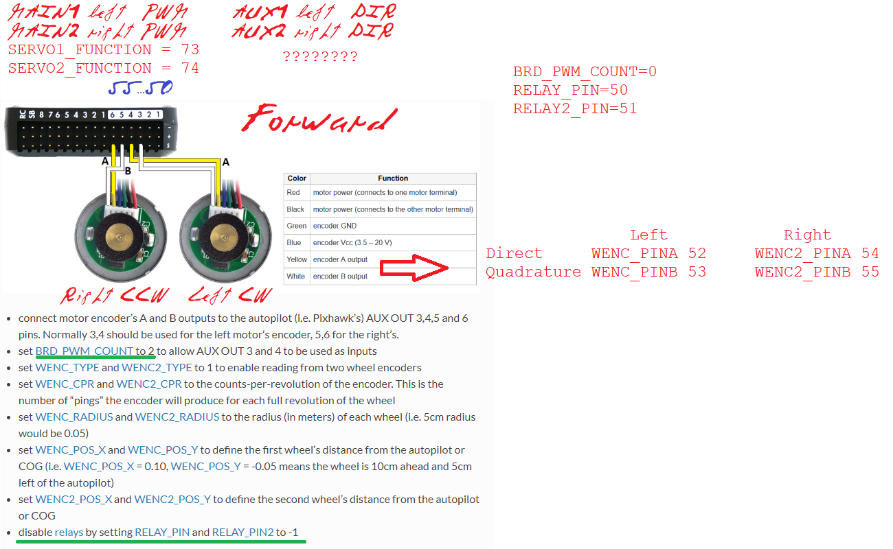
    a) Wheel encoder fix to use both wheel encoders (if present)
    b) EKF failsafe and pre-arm checks fixed when only wheel encoders used for non-GPS navigation
    c) Pre-arm message fix to reports AHRS/EKF issue (was blank)
    d) BLHeli fix to RPM calcs and telemetry (aka 0x8000 error)
    e) SET_YAW_SPEED in Guided mode made consistent with Auto mission command handling (yaw in degrees, speed in m/s)
    f) Barometer PROBE_EXT parameter description improvement
    g) Pixhawk4 board LED brightness fix

Thanks very much to all the developers, beta testers, documenters and others who contributed to this release!

7 Likes

Nice! Did not have time to test rc4 so moving to stable.

Did anything change regarding dshot?

@OldRaven, nothing fixed regarding DShot on the Matek boards but it’s still on the to-do list to resolve. It affects Copter as well if that’s any condolence so we will sort it out eventually.

@rmackay9 for a skid steer rover, what are the advantages of enabling wheel encoders in ardurover? Mine is a a 150kg rover with 2 wheelchair motors. Right now I’m using a compass and an RTK GPS to navigate, and it’s working quite well, especially on long straight segments where I’m getting 6-10cm tracking variability between runs using a RTK correction source that’s 21km away. I am in the process of adding a 2nd GPS to replace the onboard compass.

Based on your knowledge of how the encoder data is used in the autopilot software, would you expect that wheel encoders would improve the accuracy of the vehicle’s navigation? In what ways or in what sort of scenarios or maneuvers?

For me the maneuver with the most room for improvement is pivot-in-place. When pivoting on a lawn, especially on a particularly uneven surface, the rover can sometimes be 10 or 20 degrees off after a pivot, which causes a slight tracking error when it departs that waypoint for the next waypoint. Another maneuver with room for improvement is short segments (on the order of 1 meter). On short segments sometimes the rover overshoots or undershoots the end of the segment by 10-20 cm.

Relatedly, I’m using the roboclaw motor controller (controlled by PWM outputs from my Pixhawk), and it has the capability to use encoders itself (although roboclaw supports both velocity and position modes; I would just use the velocity mode). What are your thoughts on using the roboclaw encoders vs the ardurover encoder?

Thanks in advance! If any of this is written down anywhere then please feel free to point me to it…

@Christopher_Milner,

I don’t think the wheel encoders will help with the two issues you’re seeing (pivot-in-place and short segments) because I think these are control issues rather than estimation issues. I think the vehicle probably knows it’s heading but the issue is that there is a difference between the heading to the next waypoint (which is the direction it turns to during a pivot turn) and the target heading back to the line between the origin and destination.

@lthall is planning to resume work on the “S-curves” for Copter and Rover in the coming months and I hope this will resolve some of these problems.

As a refernce, I’ve uploaded a diagram I often use at the drone school to show developers (or pro users) the major components of the system. It’s not super helpful but often new developers (or users) focus on the incorrect part of the system when trying to resolve a problem.

2 Likes

Thanks @rmackay9. I observed the problem you describe (difference between the heading to the next waypoint and the target heading back to the line between the origin and destination) much more when the GPS antenna wasn’t located exactly between the 2 powered wheels (which is the center of rotation when pivoting). When the antenna was 15cm in front of the center of rotation, pivoting would move the GPS antenna along an arc (rather than rotating about a point). This resulted in the GPS antenna being located to one side of the line between the origin and destination at the end of a pivot (as long as it wasn’t exactly a 180deg. pivot). Moving the GPS antenna exactly between the 2 wheels helped this a lot. Next time I’m up and running I’ll send a logfile. But I’m deprioritizing the encoders for now…

2 Likes

You can enter offset values for the GPS antenna position.

4 Likes

I’ve disabled all compasses on my little wheel chair rover. Using GPS position and the wheel encoders I get very good heading estimation (with bad compass health warnings, though). The tradeoff is that the rover heads in a random direction for 2 to 3 feet while it determines its heading, corrects its orientation, and then runs like a charm. This was on an asphalt surface though, with more wheel slippage on grass your mileage may vary.

I think it would be cool if there was a way to have Ardupilot read the compass values for an initial guess for heading, but then rely on GPS position and wheel encoder measurements for heading thereafter. I find the compass reliability and consistency is not very robust, at least the way I’ve got my rover set up.

I second your desire for more pivot in place functionality. Any new developments on your mowing rig?

1 Like

What’s this “drone school”? How much is the tuition? :grinning:

@MisterMower,

The drone schools is listed here on our training centers wiki page and I train students on how to modify the ArduPilot software to do what they want. New flight modes, new features, etc. I think tuition is about $1000 for 4x 3h classes. The school is based in Tokyo so difficult for many to attend but much of what I teach ends up on the developer wiki.

1 Like

Drew, a bunch of changes in progress but none complete, will let you know…

I assembled a balance bot with stable v4.0, with wheel encoders.

I always got rpm1 and rpm2 0:
rpms400
(This also happened with latest version).

Going back to v3.5.2 rpm’s appeared:
rpms352

Hi. Thanks for your answer.

Unless I am still seeing an old version of “Ground testing” here, ‘another’ would mean that in v4.0 on you could do the test both ways. v3.5.2 permitted do an easier test of the encoder signals (in fact, rpm1 and rpm2 change even moving the motors by hand). MAVlink distances are not very informative.

For the motors I use, CPR is not clear, so I wanted to adjust it with a tachometer. So I installed v3.5.2 in a spare pixhawk, and connected there the encoders. With rpm1 and rpm2 I could get values for WENC_CPR and WENC2_CPR (rpm1 and rpm2 as appears in tachometer).

But there is not much information about the connection of the encoder signals. Note that with two motors (left 1 and right 2) there is an asymmetry since for forward movement the left motor (seen from left) turns CCW and the right one (seen from the right) turns CW.

Here appears:
…for rovers with skid steering, “Test motor C” should cause the left wheel to turn forward. “Test motor D” should cause the right wheel to turn forward.
but that doesn’t give indication about encoder signals.

This motors test works for me, and in adition with the vehicle seized, leaning it forward the wheels moves forward and leaning it backwards the wheels move backwards.

For considering the left and right motors asymmetry mentioned above I use:
WENC_PINA,53
WENC_PINB,52
WENC2_PINA,54
WENC2_PINB,55
with:
52 (AUX3) going to left motor C1,
53 (AUX4) going to left motor C2,
54 (AUX5) going to right motor C1,
55 (AUX6) going to right motor C2,
(C1 and C2 are the labels on motor encoder signals)
but I cannot find information about if this is correct.

For directions:
MOT_PWM_TYPE,3 (BrushedWithRelay)
RELAY_PIN,50 (AUX1, left motor)
RELAY_PIN2,51 (AUX2, right motor)

For motors PWM’s:
SERVO1_FUNCTION,73 (left)
SERVO2_FUNCTION,74 (right)
better than what appears here (SERVO3_FUNCTION, 74), since in this way connectors are all together and tighter.

But the vehicle is not yet stable even with no RC inputs: it moves back and forward and falls.

This is a log with the vehicle armed (transmitter off (no RC)), first seized by hand and leaned back and forth, and then released on the floor partially (if released completely it goes away and falls: it is unstable):


This happens even with a small battery, placed as low as possible.

Varying PID parameters:
MP_basictuning
doesn’t change too much this unstable behaviour, so I suppose I have some parameter completely wrong. What can happen?

BTW1
GPS: u-blox 1 saving config
EKF3 IMU0 started relative aiding
u-blox 1 HW: 00080000 SW: ROM CORE 3.01 (107888)
fmuv3 004D0032 3238510C 38383435
ChibiOS: 0997003f
ArduRover V4.0.0 (0e52bafa)

BTW2, it seems that default BAL_PITCH_MAX is 10, but in the rover full parameters list is at most 5:

Hi! For the balance bot, you will have to tune three sets of PIDs for balance, speed and turn rate. Only balance PID is used by the vehicle when it is in Manual or Hold mode. Wheel encoders are used mainly for speed and turn rate control and is not “necessary” to balance. So if your vehicle is unable to balance, you may have to retune the balance pids. It seems the balance PID parameters are not shown on the mission planner tuning tab, but these can be be accessed from the parameters tab. You can find more about balance bot tuning here: https://ardupilot.org/rover/docs/balance_bot-tuning.html#balance-bot-tuning
I would recommend that you read the balance bot wiki before you proceed(especially common issues):
https://ardupilot.org/rover/docs/balance_bot-home.html

1 Like

Hi. Thanks a lot for your answer.

From the tuning page:


I suppose that I must concentrate in B and not in A in MP.
What does the “PID tuning plot” refer to in MP?

About the “common issues”, my backslash is 1mm measured on the outer part of a 65mm diameter wheel (those used in 1/10 R/C asphalt racing). With a geared motor it is difficult to reduce it.

Some thoughts:

Thought 1:
I use a motor controller with DIR and PWM signals. It has been asked if a L298N Dual H-Bridge Motor Controller could be used which has signals for direct transistors bridge control. So inserting some TTL logic:
In1 = PWM1 * DIR1
In2 = PWM1 * /DIR1
In3 = PWM2 * DIR2
In4 = PWM2 * /DIR2
although perhaps it is better to use a microprocessor calculating above functions and aditionally braking the motor during some milliseconds when DIR1 or DIR2 changes.

Thought 2:
For no backslash perhaps the philosophy of crawlers with motor on wheel could be used, with motors as those used in gimbals. An rpm counter as those used in helicopter governors attached to the ESC’s could be used for velocity feedback.

Thought 3:
My plan is to emulate this on the balance bot using a RTK GPS (the track is narrow), in fact one of those on seen on the car roof.

Yes, B is the correct way.
Yeah, I don’t think anything can be done about the backlash if you’ve already bought the motors. But see that you have configured minimum throttle. You had also mentioned that you’ve moved the battery down. That may not always help, and in fact can also have a bad impact on the balancing performance.

To use the PID tuning plot in MP, this might help: https://ardupilot.org/rover/docs/rover-tuning-throttle-and-speed.html#desired-speed-to-throttle-pid-tuning. This is actually a tutorial for tuning speed control. For tuning balance, set GCS_PID_MASK to 4 instead of 2.

I’d say L298 is too much of a hastle, if you already have a motor driver with pwm, dir input. There are geared motors with encoders that are rated zero backlash. Still, I haven’t tried one of those yet. Auto missions should work fine with balance bots.

1 Like

Hi. Thanks again for your answer.

Varying parameters on B at least I see stability changes, but the vehicle is not still stable with no RC inputs: it moves back and forward and falls.

Motors used are 620rmp 12V that with 65mm diameter wheels should go up to 2m/s at full modulation.

I am using the Pololu 2519 dual motor controller (though it doesn’t provide much current):


which receives PWM and DIR signals ((M1/M2 signals to left/right motor)). The problem is that I cannot find documented where to connect the DIR signals and how to define its connection. So I did the following (pixhawk), supposing that RELAY_PIN would control the left motor direction an RELAY2_PIN would control the right motor direction:
DIR1 (left motor) to AUX1 (50)
DIR2 (right motor) to AUX2 (51)
BRD_PWM_COUNT=0 (all 6 AUX’s GPIOS, 2 outputs (1, 2) and 6 inputs (3, 4, 5, 6))
MOT_PWM_TYPE = 3 (brushed with relay)
RELAY_PIN=50
RELAY2_PIN=51
Other RELAY’s (3 to 6) -1 (GPIO inputs).

This doesn’t work: although DIR pins change, it seems as if different parts of the program fight with the DIR signals.

But if I adhere strictly to Wheel Encoders Connection and Setup (which says nothing about DIR connection for this type of control) with:
BRD_PWM_COUNT=2
RELAY_PIN and RELAY_PIN2 -1
motors direction doesn’t change. Is that definitely correct for this type of control?

I include here my interpretation of connections in that page, including other parameters. Please, indicate what I am interpreting the wrong way.

Green: doubts mentioned above.

From the encoder side, forward implies left motor CW (direct before quadrature), and right motor CCW (direct behind quadrature), or could be all the opposite.

What am I doing wrong?

On Copter v4 rpm1/rpm2 representation still works (and beautifully), since it is important for governors. See Helicopter Rotor Speed Governor.

For helicopter governors the rpm library is called internally from the main code and applied in the RSC object. It is not sent over MavLink.