Hello everyone,
I’ve been trying to setup a broadcast mesh network across 6 nodes using RFD900x modules. One node is supposed to be the GCS. I have started with running MultiPoint 2.75 firmware and observed big latency when connecting to GCS software both QGC and MP. After upgrading to 2.86 firmware I have measured connection period and the observed stream rates indicated in Mission Planner,
For 2 nodes network running ArduCopter 4.0.0, connection period was about 50 seconds and stream rates was changing 0.3-0.7Hz back and forth for most of the mavlink messages. It looked the same with ArduPlane 4.0.5 firmware.
For 3 nodes network running ArduCopter and ArduPlane respectively, connection period was the same but interestingly I observed better performance in stream rates for both vehicles. Most of the messages were having 1Hz and some of them 0.7Hz.
Compared to 3DR SiK Radios, RFD900x throughput is lesser, in terms of measured stream rates. Do you see any problems or have any suggestions?
For the 4th node, I first tried to connect one-to-one to gcs, But I GCS become stuck in parameter download in both MP and QGC.I don’t know why, configurations were the same. And link quality was around %20-30 in Mission Planner. I will update this post for 4 nodes. UPDATE: I changed nothing but powered all radios at the same time! After that forth node become responding the same as others. Stream rates were the same with 3 node configuration. Seems like network works reliably until now. Right?
The LED on the radio which is attached to GCS is blinking but remote nodes are having steady green light which means that it established the connection successfully. Is blinking green LED normal for GCS module?
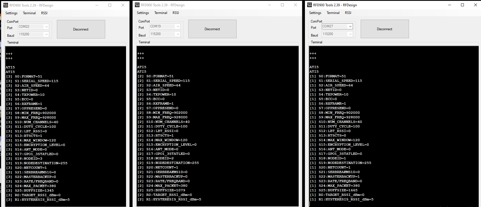
I think there is lack of documentation of these sick radios, in terms of parameter explanations. For example S22, MASTERBACKUP, is not even mentioned in latest MultiPoint firmware. And I could not figure out the actual functionality of the parameters R0, R1. I don’t think one sentence description is really explains the parameter.
MAX_PACKET and BUFSIZE are the other ones which are not documented, and they seem to be changing without modification! I did not make any changes but both parameters seem to be being set by module itself and they are different, I don’t know why.
For parameters DUTY_CYCLE and MAX_WINDOW, I don’t know which value to choose and their metric information do lack. I know duty cycle is expressed as percentage but percentage of what signal? And max window does not give me any clue, maybe because I lack knowledge on RF communication. Hopefully someone would give me ideas how to set these parameters. I know, I should test. But how can I measure the performance?
I have activated RTS/CTS for the modules which are attached to pixhawk cube running ArduPilot. I observed small difference in performance, but RTS/CTS seem to be fooling the GCS software. I have TXPOWER=10 just for indoor tests.
So, do you see anything wrong in my setup? I am open to any advices which may result in better performances across the network for 6 nodes. I thought higher baudrates than 115200 will give much more bandwidth for reliable MAVLink traffic when having high number of nodes without having overflow in RX/TX buffers and locking the traffic. But RFD900x baudrates higher than 115200 does not match actually with Pixhawk hardware (???). Only serial0 seems to be the only port that match the RFD900x baudrates but it is placed at the left side of pixhawk and on micro usb port! Any ideas for configurations are welcome.
Have any of you considered to give a try to AsyncMesh? I read that AsynchMesh firmware having more packet loss compared to MultiPoint.
These are my experiences so far. Thanks in advance.
UPDATE
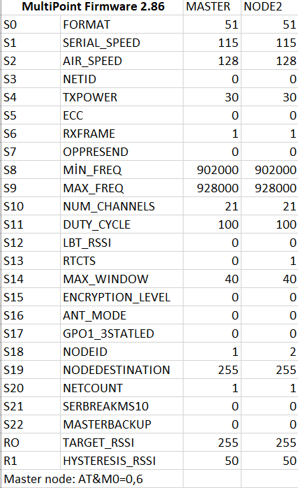
There is a AT command which specifies the number of nodes in the network and that must be configured only for master node. AT&M=0,Z
I tested 1 to 1 connection with master node having AT&M0=0,2 and result is perfect! I observed the parameter download time around 20 seconds and measured stream rates in MP was almost the same as requested rates, e.g ATTITUDE 4Hz.
Increasing the parameter AT&M although you don’t have that much of nodes connected, it decreases the throughput with the same air data speed parameter on RFDs.
@eminakgn When you got everything configured correctly, did the status lights go solid green on all radios including the master? My master is blinking green and the slave is solid green.
RFD suggested me to try configuring example for 7 non master nodes in manual. I tried and throughput is x3 now but still not at %100 of expected, it is around %80. But it seems sufficient for now. I will update for further news.
I emailed RF-Design and they noticed that I had the masterbackup set to 1 (based on an article I saw that recommended that). I set it to 0 and restarted the radio and the light turned solid green.
“The blinking indicates when this node is active because no other master node was detected on the network.”
I came across the same article and mine is set to 1 as well. So master node is not supposed to set masterbackup param. Thank you for you contribution! I will test it.
I discussed with RF-Design and here is my latest configuration for 5 non-master node broadcast network that can get around %80 of the payload with default stream rates provided by Mission Planner and decent connection speed. But I could test with only 3 non-master nodes on the table since I did not receive the last 2 modems yet. I will go for range tests for now.
Also I tried to measure the transmitted bytes per second from 1 autopilot. It was around 4Kbytes which will preserve 20Kbytes per second for 5 nodes. With 115200 bauds, around 14Kbytes can be transmitted. So I predict 115200 bauds will be the limiting factor when 5 nodes connected at the same time. But I could not figure out how to overcome this situation since RFD900x modems do not support higher bauds for pixhawk. Any ideas?
Does the AT&M=0,Z command change S20: netcount to whatever Z value is? I.e. seven nodes including he master would be Z=7 and the displayed netcount would be 7? I’m putting in the AT&M=0,7 command but the netcount is not changing from 1.
OK, nevermind. S20 in number of networks, which i have 1. The AT&M=0,Z is the number of nodes within the network. I put in the command and it said OK, then i wrote it and it said OK, can’t see where it would be displayed but i’ll trust its in there.
I got it to work but they are all showing up and popping in and out. Is there a way to select one at a time to send commands to? I’ll be flying 6 at once and need to be able to select and command one at a time. Thanks.
Update: I got it working now, you have to set each aircraft’s “SYSID_THISMAV”, i.e. aircraft sysid 1, aircraft 2 sysid 2, etc. Then they all show up as individual aircraft that you can select.
Could anyone refer me to a very basic instructable/how to in order to get setup. I’m new to Ardupilot and RC control. We’re driving individual USVs successfully but now need fleet control (6 vessels) from a single transmitter. I think the requirements are not dissimilar to yours, @eminakgn, and, at least in our case, are very simple: Give each USV a position to go to then loiter. Every now and then give them new positions at which to loiter. At the end of the day, RTL. Only minimal telemetry is required from the USVs - eg SoC, position.
Thanks in advance.