RFD900+ not connecting to Pixhawk2.1

Just received a brand new RFD900+.

It won’t connect to my Pixhawk2.1, meaning MissionPlanner will timeout when trying to connect.

But it works just fine with a Pixhawk1.

Using Telem1 on both. Triple checked RX/TX pairs.

Here’s a screenshot that shows MissionPlanner tells me the two radios see each other though.

I’ve compared the SERIAL1_* , SR1_* , and SER1_* parameters between the two Pixhawks and they’re the same:

SERIAL1_BAUD,57
SERIAL1_PROTOCOL,1

BRD_SER1_RTSCTS,2

SR1_ADSB,5
SR1_EXT_STAT,2
SR1_EXTRA1,4
SR1_EXTRA2,4
SR1_EXTRA3,2
SR1_PARAMS,10
SR1_POSITION,2
SR1_RAW_CTRL,1
SR1_RAW_SENS,2
SR1_RC_CHAN,2

Param file of Pixhawk2.1: Dropbox - v2.1-2017-08-31.param - Simplify your life

Parma file of Pixhawk1: Dropbox - v2.0-2017-08-31.param - Simplify your life

Pixhawk2.1 is using ArduPlane 3.8.0, Pixhawk1 is using ArduPlane 3.7.1.

Anyone experiencing similar issues with Pixhawk2.1? @proficnc ?

Thanks

Both radios are showing solid green lights? I’ve been using these exclusively with Pixhawk 2.1 for several months including 3.8. If you’ve got solid green on both I’ll take a look when I get to the hangar in the morning.

@Todd_Bagley

Yes, both solid green lights, with the Pixhawk 2.1. MissionPlanner won’t connect (times out).

With the Pixhawk 1, green and high freq orange flashing (for data transmission, apparently).

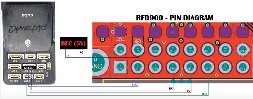
That confirms that at least the two radios are definitely communication with each other. Are you using a cable for the Pixhawk 2 that you put together yourself? If so,have you validated the pin order and that the Rx and Tx pins have continuity on both ends? Here’s a diagram in case that “might” be an issue. Ignore the power and ground if you have it different but the others are what I’d check.

I have a RFD 900 (note, not a 900+ but I don’t think that matters) with a cable as @Todd_Bagley shows in the diagram and it works correctly on a PixHawk 2.1. (Thanks for that Todd_Bagley!)

I’m having the same exact issue. This occurred the moment I upgraded to 3.8 and upgraded to latest Mission Planner. I haven’t been an able to find a solution. I had to downgrade to 3.7 again.

@Todd_Bagley : yes, put together cable. I’ll double check. We have a jumper between #4 and #6. Not a BEC for #2 and #4. That same wiring works with Pixhawk1 though (different cables though).

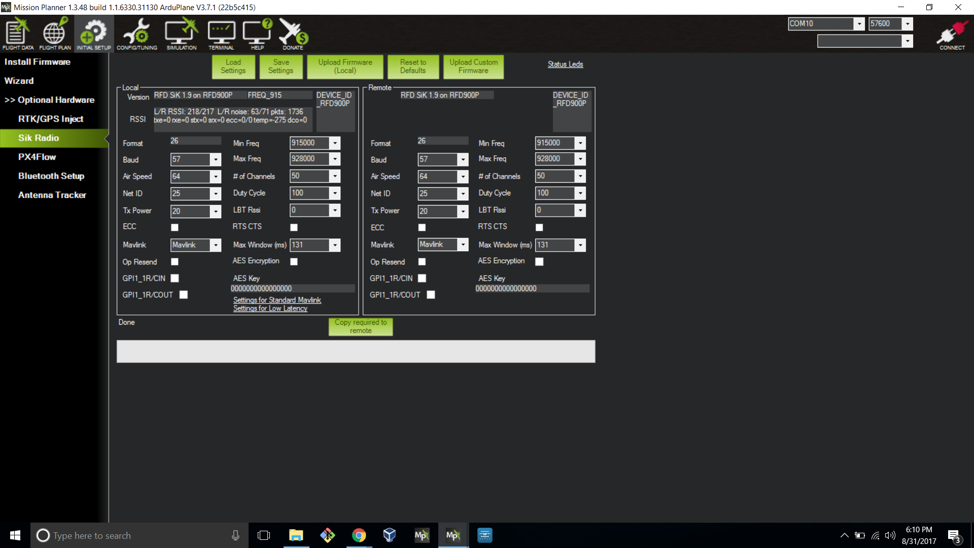
@hunt0r : ArduPlane? ArduPlane? which version? Could you provide your param file or the SERIAL1_* , SR1_* , and SER1_* parameters you use please? Thanks

@Alexander_Perez : Pixhawk2.1? Param file?

I have it working right now with a PixHawk 2.1, ArduPlane 3.8.0, Mission Planner 1.3.49, RFD 900’s on both GCS and PH. (note: not RFD 900+… in case that’s the difference?)

SERIAL1_BAUD = 57
SERIAL1_PROTOCOL = 1
SR1_ADSB = 5
SR1_EXT_STAT = 2
SR1_EXTRA1 = 4
SR1_EXTRA2 = 4
SR1_EXTRA3 = 2
SR1_PARAM5 = 10
SR1_POSITION = 2
SR1_RAW_CTRL = 1
SR1_RAW_SENS = 2
SR1_RC_CHAN = 2

I don’t see any SER1_* parameters but I do see BRD_SER1_RTSCTS = 2, in case that’s relevant?

I am pulling the 5V (Todd’s BEC) from my PH2.1 servo rail.

Alright it’s working now.

Had to swap RX and TX, following @Todd_Bagley’s diagram.

We were initially following that doc, with has RX and TX reversed. sigh

https://www.dropbox.com/s/1rzjsxzrzx8onf9/PixHawk%202%20Connector%20Pinout%20-%20Leo%20Technologies.pdf?dl=0

Thanks all for your help!

1 Like

I have an RFD 900+ and it’s not working for me. I’ve tried also various RFD 900+ firmwares and nothing.

Oh, right, I’ve made that mistake before. The PH’s TX needs to be wired to the RFD’s RX (not to the RFD’s TX), and vice-versa.

1 Like

I’m using firmware 1.9 on my RFD’s. (I think it’s outdated, but it works.) So @Alexander_Perez do I understand correctly that for everything else held constant (same MP version, Firmware version, Pixhawk, same cable, etc.), your RFD’s work for ArduPlane 3.7 but not for ArduPlane 3.8?

@hunt0r I haven’t tried with the mentioned mission planner yet. I will try with the same mission planner build. Hopefully that should work. Thanks

Thanks Todd making this diagram!
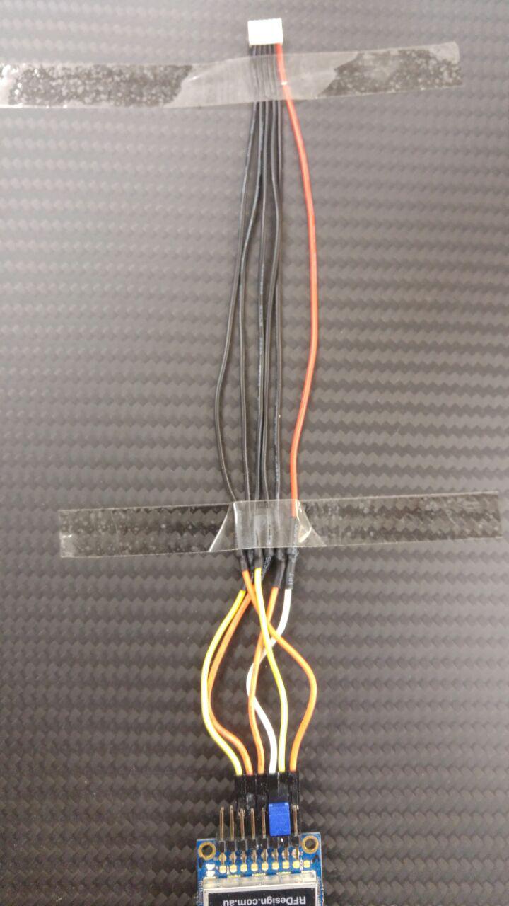
Here is one additional image which shows how ready made cables are put together. I made this referring images online and without physical cable in hands.
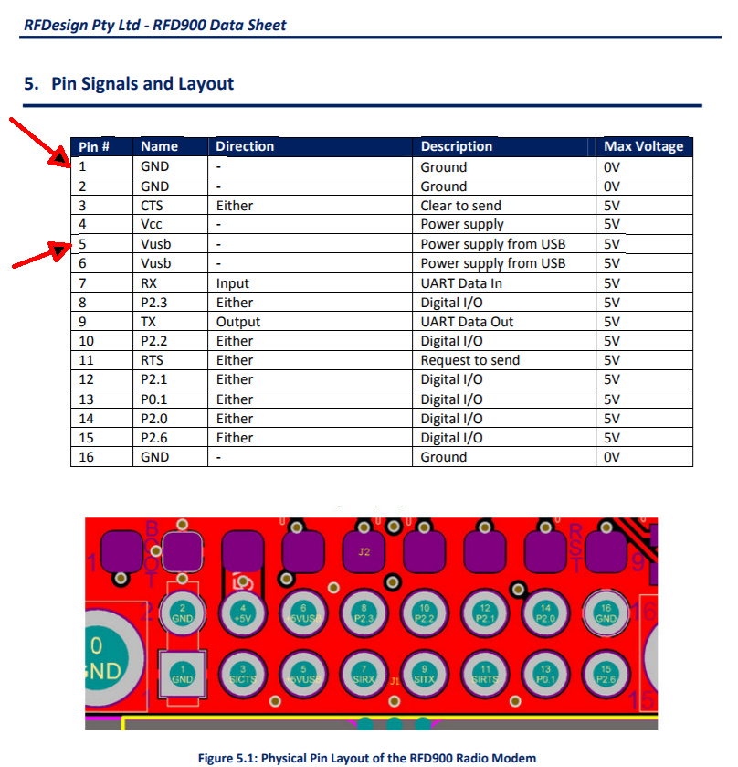
AP + = RFD900 pin 5

AP - = RFD900 pin 1

With this connection radio modem is powered from Pixhawk (Image from RFDesign documentation):

This is from Leo Technologies documentation:

Here is setup how RFD900 did connect with Pixhawk 2.1. Jumper was needed too on both radios.