I am looking for recommendations for a tutorial to build a rover. The tutorial on this site was not what I am looking for and I don’t know if anything better exists but, ideally, the tutorial would start with a list of required and recommended equipment, an expected host vehicle configuration and the necessary accommodations for deviations from this configuration.
I have a stock traxxas rustler with an upgraded but brushed motor, 7 cell nimh battery (8.5v), stock esc, servos and 3 channel receiver, so if there is a tutorial with this host configuration, that might be ideal.
Alternatively, my specific questions from this tutorial are:
Can I keep my normal controller/transmitter (since I am used to it)? I don’t know if there is a way to take control from the autopilot with my standard transmitter. I was hoping there is a way to disarm it if any input from the throttle (or steering) is received.
Can I use the standard motor/esc - do I need a separate BEC for the autopilot? Can I drive the steering servo with just the autopilot?
Do I practically need a zigbee (or similar) to talk to the autopilot or will a usb cable suffice?
Your standard motor/esc should work just fine as long as it can accept PWM input. I’m assuming your ESC is providing power to the servo, so connecting them both to the servo rail of the autopilot should do the job for the servo. If it’s the nimh battery providing the power to the servo, that will need to be connected to the center pins of the servo rail. Most autopilots (like the pixhawk) really should have (and some NEED) a separate BEC to power them. Autopilots like the cube often come with a “power module” that can sense battery drain, and they include a built-in BEC. It provides a clean 5 to 5.3V power to the autopilot to run smoothly.
A USB cable will suffice, however it is usually really difficult to tune an autopilot for autonomous control with a USB cable attached. Some 900MHz 100mW 3DR SiK radios might do the trick without breaking your wallet.
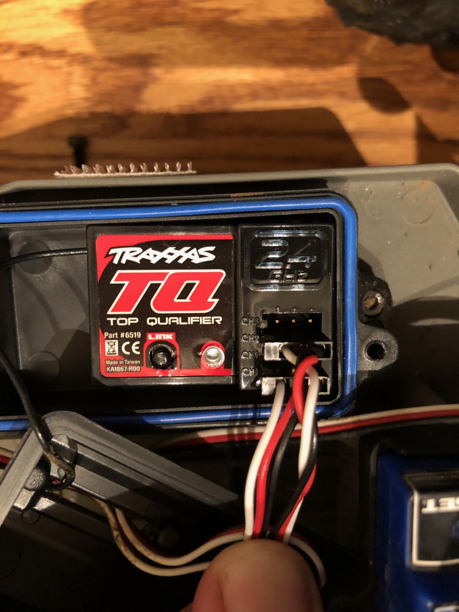
My receiver uses pwm @ 1600 hz so I would need a converter to go to ppm-sum, right? What would that allow me to do? Run the output of the receiver through the autopilot to the servos? It looks like the steering servo is run by the receiver as there aren’t any wires going between the esc and servo
Yes, sparkfun is very popular. Is your tranmitter compatible with any newer receivers? It may be simpler to just upgrade to a new receiver, but I understand if you want to keep the same TX/RX combo, then a PPM-Sum receiver may be your only option.
I’m confused how your ESC is getting its throttle input if it is not connected to your receiver; could you explain more or maybe attach a picture of your setup? Normally the receiver sends the signals to the autopilot, and depending on the mode, the autopilot decides what to output. By the way, you may need a third channel to send the mode. MANUAL mode will basically pass-through all commands from your RX to your servos/ESC. Other modes will apply some sort of correction to the signal to try to help your vehicle achieve a specified heading and velocity based on your inputs. AUTO mode will take full control of the vehicle and attempt to conduct a pre-defined mission that you have created and uploaded to the vehicle.
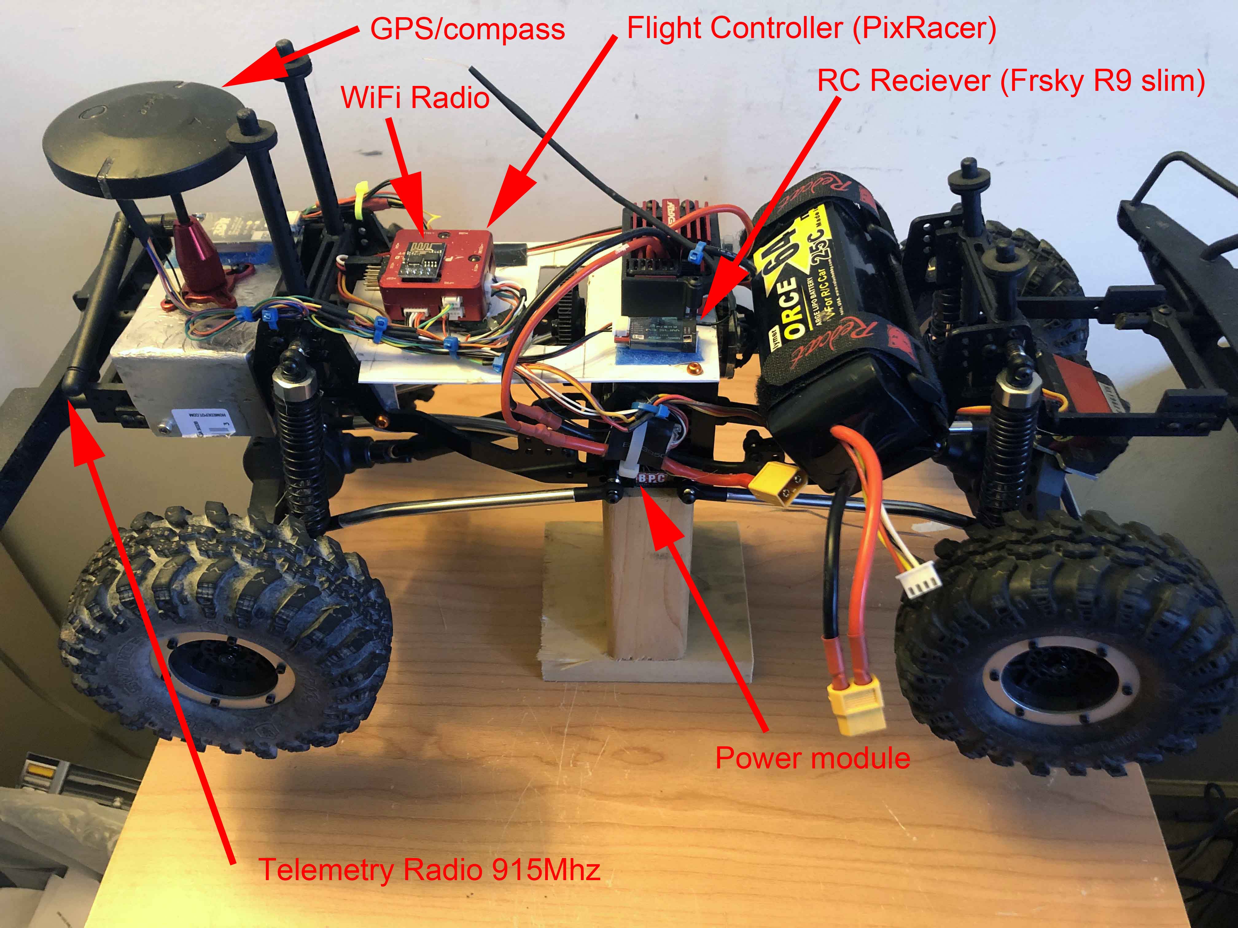
The ESC is supplying power to the Receiver which in turn supplies power and signal to the Steering servo. You will need at least a 3 channel RC system, 4 or more can be useful. I have built Rovers from a couple different off-the-shelf RC Trucks that are essentially no different than that vehicle and it’s a straight forward conversion. I used PixRacer FC’s but you can use any from the following list. The “Closed Source” choices can be relatively cheap:
Space will be at a premium on that truck and one FC that’s not on the list that is supported and would would work well is a Kakute F7 mini. It’s what I would use for a new build if I didn’t have a a drawer full of others FC’s.
These trucks are mostly setup the same. There are 2, 3-conductor servo leads coming out of the Receiver box right? One goes to the esc carrying the throttle signal on the white wire and the ESC is feeding V+ back to the receiver on red and black. The other cable is carrying the steering signal and V+ to the steering servo. The 3rd channel is likely not used and on some Transmitters there isn’t even a control (switch, pot, etc) to control the 3rd channel.
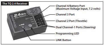
All you need is a Flight Controller, a GPS module and depending on which FC you choose a power module. But again you really want more channels than the typical RC Truck radios have. As was stated a channel for drive modes, an Arm switch is nice, a Save Waypoint switch is nice.
It’s the same output for steering (dual). Probably to allow for a dual steer vehicle option. And that 3rd channel is only controlled by an off/on switch on the Transmitter which will not work for flight modes. Well, it would give you 2 modes which really isn’t enough. You will want another RC system.
Could you please share your opinion on this design? I need to be able to quickly return the truck to it’s normal configuration because, well, it belongs to my son. The main idea is that I would just add a connector inline with the motor drive wire and the servo steering wires.
A plexiglass plate would hold all the UGV components and takes the place of the truck body. The plate could have a separate lipo to power system components to facilitate bench testing because I don’t know how much power these components will draw. Maybe the 7 cell 8.6 volt onboard battery can power both the car and equipment? I could always use a USB power board for bench testing.
If I use the onboard battery, can I power the UGV equipment through the ESC? I think it produces a 5v signal to send to the receiver but I can’t find a spec sheet to know for sure.
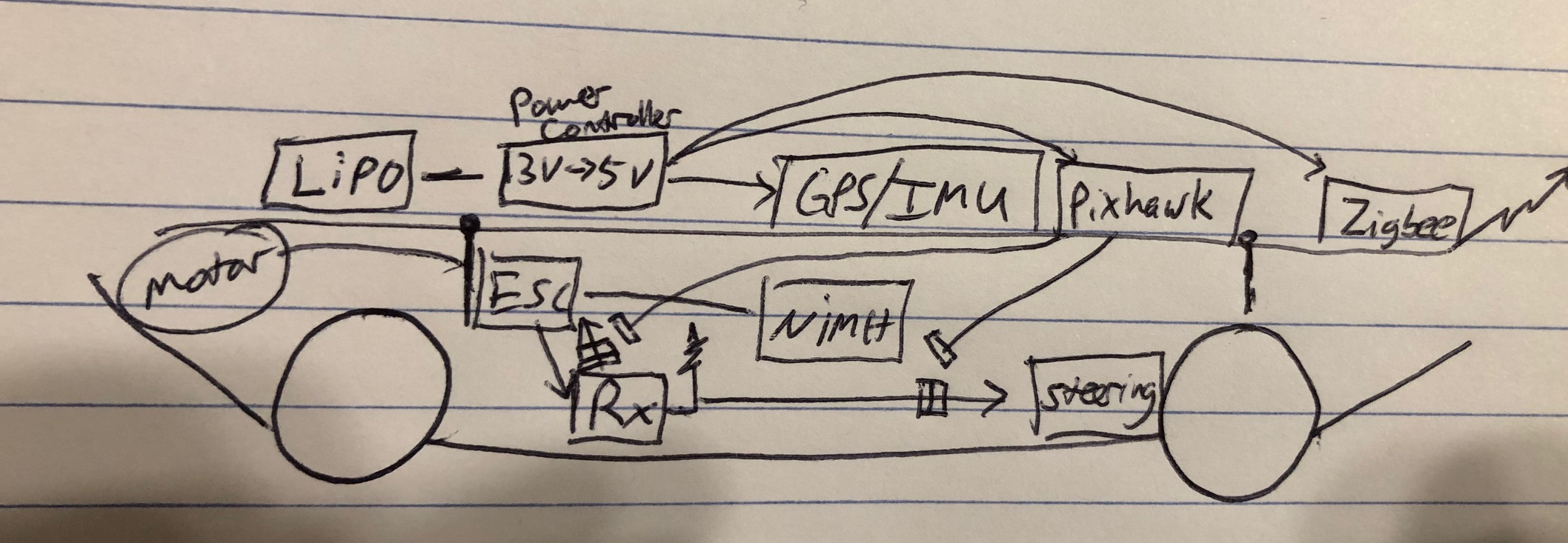
Also on the board are a GPS/IMU, a flight controller, and a zigbee radio to talk to my computer.
My honest opinion is that these autopilot systems are not designed to be removable, and you would be much better suited to start with a basic system and get it running before trying to make it entirely removable. Yes, it’s possible to do it, but baby steps are honestly the fastest way to get there, and it will avoid a lot of frustration. Build a test-bed vehicle to prove to yourself what can be done. When you are ready and have your lessons learned, then you can step it up.
From your diagram above, there are several suggestions that are probably also addressed in the video below. First, the Pixhawk IS the IMU. The GPS is normally a GPS/compass, NOT an IMU. Normally the power controllers are in-line with the main battery to avoid needing two separate power systems. Basic low-power radios like 3DR SiK radios can be run straight from the pixhawk without external power. As mentioned above, you would probably need a separate receiver to use the one-wire protocols.
Thanks for the build video - it was really helpful. Are the part numbers of the components you used listed somewhere? In particular, what was the power controller you selected?
Thanks!
Attached is one I built for reference. Bolt a plate to your truck and locate all the hardware on it. The stock body shell fits on this it may not on yours. You could choose a Flight Controller that takes battery voltage directly then you wouldn’t need a power module. And there are much smaller GPS/Compass modules. 2 telemetry radios are obviously not required, whatever suits your purpose.
Yes. The ESC for the motor may require a different setting or it might work as is.
You will connect the servo lead from the ESC to Main output chan 3 on the pixhawk. This will provide power to the servo rail for the steering servo as it supplies power now to the stock Rx. The throttle signal will be provided on this channel. Then connect the servo lead from the steering servo to Main output chan 1.
BTW-A pixhawk doesn’t accept discreet PWM signals as input from a receiver. PPM, Sbus, iBus, etc. only. But you will be buying a new RC system anyway so this won’t be a problem.