Thanks for this Patrick
I have ordered a TF Mini Plus as you suggested. IS there anything that needs to be done to make it work as an I2C device or does it work out of the box like that.
Cheers
Thanks for this Patrick
I have ordered a TF Mini Plus as you suggested. IS there anything that needs to be done to make it work as an I2C device or does it work out of the box like that.
Cheers
@ppoirier
I just tried my Tfmini Plus on the I2C port on my quad and no go.
I am using the correct gui.
I have checked all the connections but no go on the gui reporting or my pixhawk seeing distance.
Also to confirm This is the unit I ordered
These are my setting
RNGFND1_ADDR,16
RNGFND1_FUNCTION,0
RNGFND1_GNDCLEAR,34
RNGFND1_MAX_CM,600
RNGFND1_MIN_CM,30
RNGFND1_OFFSET,0
RNGFND1_ORIENT,25
RNGFND1_PIN,-1
RNGFND1_POS_X,0
RNGFND1_POS_Y,0
RNGFND1_POS_Z,0
RNGFND1_PWRRNG,0
RNGFND1_RMETRIC,1
RNGFND1_SCALING,1
RNGFND1_STOP_PIN,-1
RNGFND1_TYPE,25
I am experiencing the same issue. Did you ever get it working?
It never changed from grey so I just did the config in the parameters listing. This assumes the ranger finder is a compatible version.
i suggest you the tf mini s… fully compatible on serial… uart an on a can node
Since I already have the TFMini Plus, I’d like to get this working. It works fine in the benewake gui and MP (serial mode). But after following all the months of discourse, ardupilot.org, and speaking with the benewake folks, still cannot see it on MP (i2c mode). Once I figure it out I’m going to upload a simple 1, 2, 3… or as suggested get the S model.
Also, when I connect to the Benewake gui (when in uart mode), I see how to enter the commands, but don’t see the “Response” (Table 11) that the manual shows.
It is also not clear to me once it is working for obstacle avoidance, will the vehicle automatically start this behavior, or are there additional settings?
hi, did you manage to get the TFmini plus working?
I have the same problem and I have not been able to solve it.
For me I set the TFMini Plus to I2C.
Then set the parameters for the unit in Mission planner directly through the config table an not the rangefinder page. It never worked there.
So here is how to get the TF Mini Plus working on Pixhawk I2C.
Connect your TF Mini via the supplied cables to a TTL to USB adapter.
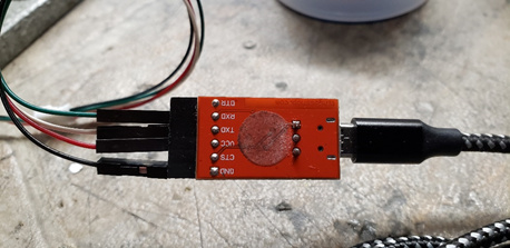
Connect via the USB cable to your PC.
If you have not already downloaded the TFMini Gui…do so from http://en.benewake.com/support
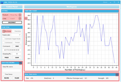
Open the Gui
You should start seeing distance information on the graph in the gui.
Using the command line function issue the following two commands by pasting each in the command line and pressing send
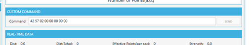
5A 05 0A 01 6A
5A 04 11 6F
The first sets the device to I2C and the second forces a save.
Nothing should appear on the graph from this point on.
Next you need to connect it to your Pixhawk or I2C hub.
Please note that the pinout on the supplied connector has the SCL and SDA reversed. You need to pull out the pins and swap them.
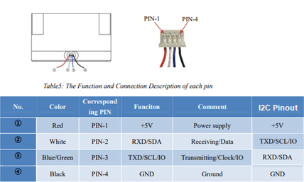
Please note the SCL and SDA are reversed.
You need to configure a few settings in Arducopter.
RNGFND1_ADDR,16 This is the I2C address for the Lidar
RNGFND1_GNDCLEAR,34 This the distance from the Lidar to the ground…easiest way to set it is to have the drone report the distance to the ground when sitting on your workbench and then enter that distance.
RNGFND1_MAX_CM,600 Set this as the max distance the device will be used.
RNGFND1_MIN_CM,30 This is the minimum distance for the lidar.
RNGFND1_ORIENT,25 This is telling Arducopter that the lidar is pointing down
RNGFND1_TYPE,25 This sets the lidar type to TFMini I2C
It should be working now.
Good luck
Hi @rickyg32 awesome findout about the reversed pinout, i was also thinking to share this some days ago .
But even with all this documentation and correct settings and wiring, MP in my case does not want to set the sonnarrang to an other value than 0 
Even if the device is found on my RPI at the addres 10 on I2C
Have you get this trouble with the tf mini plus in i2c range finder ?
@rickyg32 First I want to THANK YOU and underscore the simple instructions I’ve been looking for.
My Sonar Range show 3 meters, but it is actually 3 feet - how to calibrate?
So there are no other settings from here, and it will now automatically integrate the sonar values into EKF2 estimates giving greater weight as it descends to lower altitudes?
I guess now that I have multiple sonars, I need to also understand how to add another address.
As an aside, after many hours of reading, many attempts, and tearing my hair out, I was on the verge of returning the product(s). I exchanged three different TFMP’s, FTDI’s, cables, etc. Nothing! As a last resort I switched from my old trusty PC tower to a laptop and … it worked!! It seems my pc serial ports were pretending as if they worked when in actuality it’s time for a new pc.
Hey Jack I am glad the notes helped you out. I am sorry to say that the rest of your questions are way beyond my ability. I am using a single TF Mini for altitude on all my drones and have no experience with teh rest of what your asking. I wish I could be of more help. I am just learning about this tech myself.
@ppoirier is the Lidar whisperer, perhaps he can assist.
Also, when using a ubec to separately power it as @ppoirier has previously spoke to, how to physically do this when you have the itsy bitsy connection to the splittler?
Jack sorry not sure I understand your question. Powering the Lidar separately is easy enough to do. Just take the power wires and connect them to a ubec. Just make sure everything has a common ground.
I see the answer to my second question is provided here
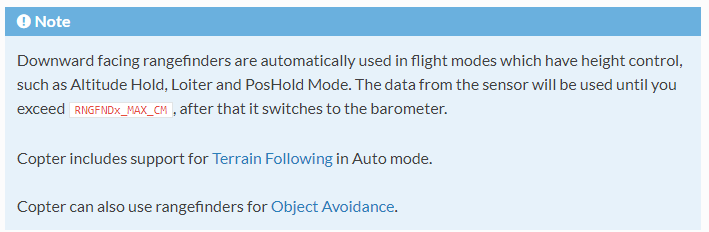
https://ardupilot.org/copter/docs/common-rangefinder-landingpage.html#common-rangefinder-landingpage
With further details here
I can certainly try to help, just put me briefly in context so I don’t have to read the whole thread
Thank you Patrick. My questions are:
What type of sonar and what interface it is connected to?
What device type have you set ?
TFMini Plus in a I2C splitter type=25 in a Pixhawk 1.
Actually I really just need help with the first question, and understand #2 and #3. Regarding the ubec, I assume I pull out the vcc and a second wire from the gnd to the ubec with perhaps a 470uF cap?