Good day, you need customize you cable… add a 680uF cap to the power lines of the sensor… pin3 from the sensor is SDA and pin4 is SCA
Don’t exceed the 5.5 volts on the sensor
It should have it’s own bec and not powered from the flight controller.
I use to have that same problem with TF minis. Not anymore…they have their own juice now
@rickyg32 Thanks for replying
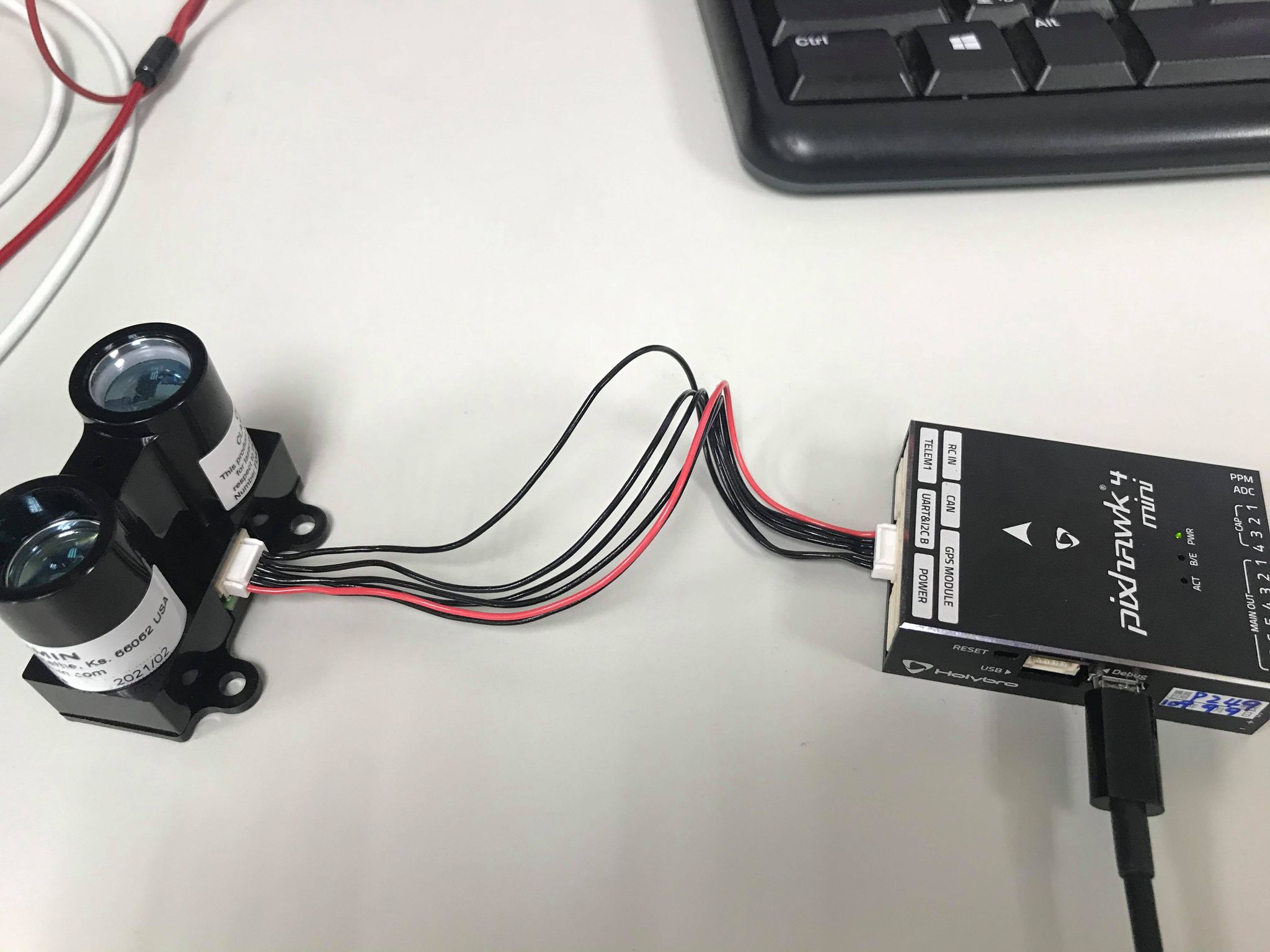
So, I need to give lidar individual power supply instead of using power pin on flight controller.Just connect sda and scl Pin to flight controller?
like the photo below
yes at least in my experience and that of a few others, the power needs to be separate. Only because the lidar pulls more then the FC can properly handle. Yes the SCL and SDA connect to the FC. My drones I use a 9am power module that feeds the FC and it’s tapped for other devices to keep the load of the fc. Weird things happen when the flight controller is not properly powered.
I think you have it.
Hi, i am having the same issue but unlike here i have right connections for lidar. I have a BEC which supplies 5v to lidar other than cube. So, what should i do ?
Some lidar are in UART mode and need to be changed to I2C.
I am no expert on TF Mini’s but I did write up some directions to get it to work if this helps.
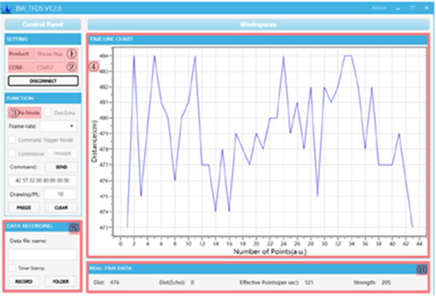
So here is how to get the TF Mini Plus working on Pixhawk I2C.
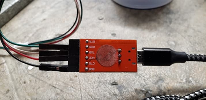
Connect your TF Mini via the supplied cables to a TTL to USB adapter.
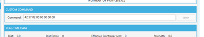
5A 05 0A 01 6A
5A 04 11 6F
The first sets the device to I2C and the second forces a save.
Nothing should appear on the graph from this point on.
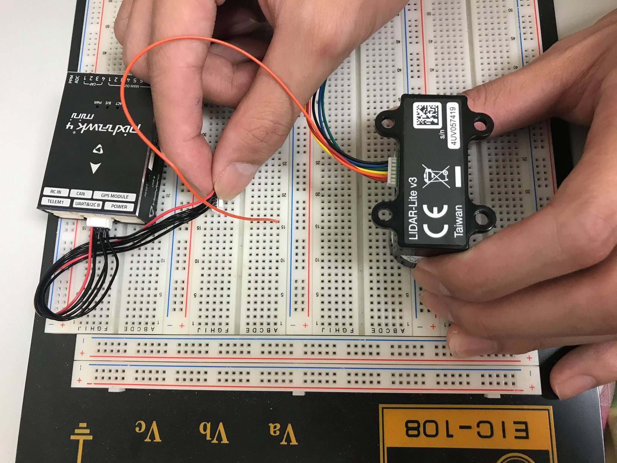
Next you need to connect it to your Pixhawk or I2C hub.
Please note that the pinout on the supplied connector has the SCL and SDA reversed. You need to pull out the pins and swap them.
Please note the SCL and SDA are reversed.
You need to configure a few settings in Arducopter.
RNGFND1_ADDR,16 This is the I2C address for the Lidar
RNGFND1_GNDCLEAR,34 This the distance from the Lidar to the ground…easiest way to set it is to have the drone report the distance to the ground when sitting on your workbench and then enter that distance.
RNGFND1_MAX_CM,600 Set this as the max distance the device will be used.
RNGFND1_MIN_CM,30 This is the minimum distance for the lidar.
RNGFND1_ORIENT,25 This is telling Arducopter that the lidar is pointing down
RNGFND1_TYPE,25 This sets the lidar type to TFMini I2C
It should be working now.
Good luck
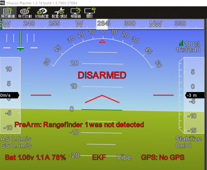
Hey I’m using ZHT 24Ghz drone altimeter radar . I’m facing a problem that is “rangefinder 1not detected” .
What will be the solution?
Please help to solve this problem