So today I installed a new ‘5 in 1’ power module / PDB (https://imgur.com/4AKhY5r) built onto the bottom dampening plate under the Pixhawk. It has powered my ESCs fine, and I had the power module plug and ESC’s attached to the Pixhawk and all appeared to be well.
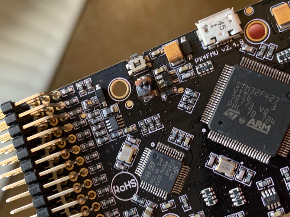
However as I was trying to get the pitch control on my gimbal to work, I disconnected the battery and noticed the power module plug was not fully insereted into the Pixhawk. After pushing firmly on it and noticing it connecting fully, I reconnected the battery and saw a spark followed by a pop, with smoke coming from the Pixhawks power module port. I quickly disconnected the battery and took apart the Pixhawk and saw a blown capacitor next to the ‘RESET FMU’ switch https://imgur.com/ybrv6kd.
I removed the debris and attempted to power the board over USB, however I just get dim green / orange main LED as seen here: https://imgur.com/xIv8UEl.
I have checked the power from the power module and nothing exceeds around 5.5V. I checked if the BEC’s on the ESC’s were blown by checking the voltage from the ESC’s and all were around 5V. I can’t think what has caused this? Was it a random power surge? Short circuit? Reverse voltage? I would presume that there is no hope for my Pixhawk and I should buy another? If so I would quite like to avoid this happening again!
Here is the latest log on the Pixhawk’s SD card. 00000124.BIN (220.5 KB) I couldn’t find any voltage spikes in this.
The power circuitry on the PCB is most likely toasted. The circled picture items are either SMT capacitors or resistors, hard to tell. What caused it, the only thing that comes to my mind is some kind of a short happened. Not sure…
are you saying you can still communicate with the board?
(Wasn’t sure how the voltage / current measurement was made!)
Do you know if there is any way to repair the PCB?
So the circled item in this image: https://imgur.com/ybrv6kd was one of the yellow A476 capacitors found across the board. I removed the debris, leaving the two terminals it attached to exposed.
A short is possible, there was a large spark across the battery just before smoke appeared.
I am able to provide power to the Pixhawk and observe those LED’s in the picture, however cannot connect to it over Mission Planner. There is no sign that the Pixhawk is trying to boot.
Replacing a SMT capacitor is no easy task. If you had a major spark and the connector got heated, this for sure means you had some kind of short circuit. A normal spark is common due to high current. triple check your wiring. You must be shorting some wire most likely at the other side of the Pixhawk and you had a feedback current and voltage loop which fried the Pixhawk. I mean Aux pins and main out pins.
Also check the PDF. maybe you dropped a tiny solder on to the board.
May not be worth to repair and then loose the entire drone in mid air
Time to buy a new one and the old one becomes a memorabilia.
Yes I feared as much. Could it have been caused by me connecting the 5V pin of the gimbal to the signal pin on the AUX pins? I remember I wasn’t particularly careful when attempting to connect the gimbal control to the Pixhawk so that might have caused a short somehow?
Either way I’ll have to wait patiently for a new one to turn up it seems!
Most likely. Depends how your entire wiring is done.
The Main Out and AUX pins on Pixhawk uses tri State logic. In plain English they stay dormant till the controller makes them enable depending if you setting them for PWM or relay. The signal pin can’t have any type of voltage source. Its an output pin. I am assuming if you have the ports enabled for Gimbal and they were set for PWM output.
Looks like a classic example of voltage looping back and frying your regulator circuitry.
No worries, we all had our fare share of smoking things. I call them cheap lighters to light up your cigars next time
So I am very confused now!! My new Pixhawk arrived on Tuesday, so I went through the unbelievably tense precedure of connecting each power-providing component to the Pixhawk individually (ensuring I connected the gimbal properly this time!), and everything seemed to work perfectly! I had therefore assumed the problem that caused the white smoke of death was me connecting the gimbal incorrectly, everything made sense!
However after doing many many tests and calibrations whereby I’ve had to power up the system from a Lipo multiple times, I decided to take it outside for its maiden flight. I plugged in the Lipo once outside and everything booted as expected, however the quad refused to arm. So, I disconnected the battery and reconnected it and, once again, a loud pop followed by ominous white smoke rising from the Pixhawk…
I am so confused! I changed nothing that time and did not even have the gimbal connected for its maiden flight. It was the same capacitor that had blown and, thankfully, I was able to bring it back to life by harvesting one of the capacitors from the old Pixhawk and soldering it in the place of the now blown capacitor. It boots up fine and I am able to connect to it once more. But I am at a loss as to how this has happened again. I also believe it has broken the GPS module.
My suspicion is it either has to be to do with having a fully charged lipo (unlikely), the power module on the PDB giving a surge upon first connecting (also unlikely as I have checked carefully) or some dodgy connection caused by me adding LED strips to the arms of the quad, with each strip being powered by the servo style connector wires coming off the ESC (powered by the built in BEC). Surely it must be some form of bad connection shorting something there? Aside from that I am at a loss!!
I’d really appreciate any help as this is becoming more and more stressful!
So on this page: https://ardupilot.org/copter/docs/common-serial-led-neopixel.html it mentions the use of a diode between the 5V supply and the LED strip. I can’t say I understand 100% the reason why this is done, but I have no included this and could this be the cause of my problems? It seems unlikely since it mentions that for most strips it should be fine. I am using WS2813 strip LEDs.
I can power the Pixhawk by USB and connect to it on the bench. On the quad I have the servo style connectors from the ESCs connected to the first four main out ports on the Pixhawk, powering the Pixhawk by the inbuilt BECs that all are outputting 5V. I have also got the power module connected to the Pixhawk that provides redundancy power, and have checked and is giving me the expected 5V. Each of these power supplies I have checked individually and are all able to power the Pixhawk fine. When the Pixhawk popped I had changed nothing to the setup, simply disconnected and reconnected the battery. I have each LED strip powered directly by the ESC servo style wires on the corresponding arm of the quad. Then the signal wire for the LED strip is connected directly to the signal pin on the AUX OUT 1-4 (Servo out 9-12).
All 3 wires from each ESC is connected. I do not know what the BEC is as I believe it is built into the ESCs. I do not have any external BECs. I had a look through the Wiki page but cannot find anything that would suggest I have connected the power incorrectly. The only thing I can think of is that a short occured in my wiring of the LED strips. It seems unlikely however as the Wiki suggests that the Servo rail can be powered independantly from the Pixhawk if a power module connector is connected (which it is in my case). Therefore I can only think that I am pushing a voltage through an output pin on the Pixhawk. I could attempt to use a diode between each output pin and the LED input?
Sorry, I meant which ESC’s do you have. You should only connect one external BEC source to the servo rail. I don’t think it has anything to do with the LED’s. Possibly a combination of the cheap power module on that integrated mount plus multiple sources of power to the Output rail. It’s a good idea to use the Zener diode on the output rail also. I don’t see you mention that in your posts, maybe I missed it. In the Wiki is says “you must” use the diode but that depends on the actual BEC output voltage. In any case it’s good practice.
Ah okay I see. No, I haven’t used any Zener diode and haven’t actually heard of that before. I also don’t see how I could get voltage higher than 5V from my ESCs. I don’t necessarily need to power the Pixhawk by the the Servo rail at all if I am getting power from my power module, so could just disconnect the power from the ESCs. What I don’t understand however is why I am only getting this problem now after happily flying before I decided to add the LED strips, camera gimbal and 5 in 1 power board.
I would not use the BEC’s from those cheap ESC’s for FC power. And if you do use only one and the Zener diode. Or just disconnect them from the servo rail.
Ah okay. In that case I will only connect the signal (and ground?) pin(s) of each ESC to the Main out rail of the Pixhawk. My camera gimbal seems to output 5V, so do you think I should connect all 3 pins of the gimbal to the Pixhawk to serve as redundancy power? Or should I just play it all safe and only use the signal (and ground?) pin(s) to the Pixhawk so the servo rail has no voltage.
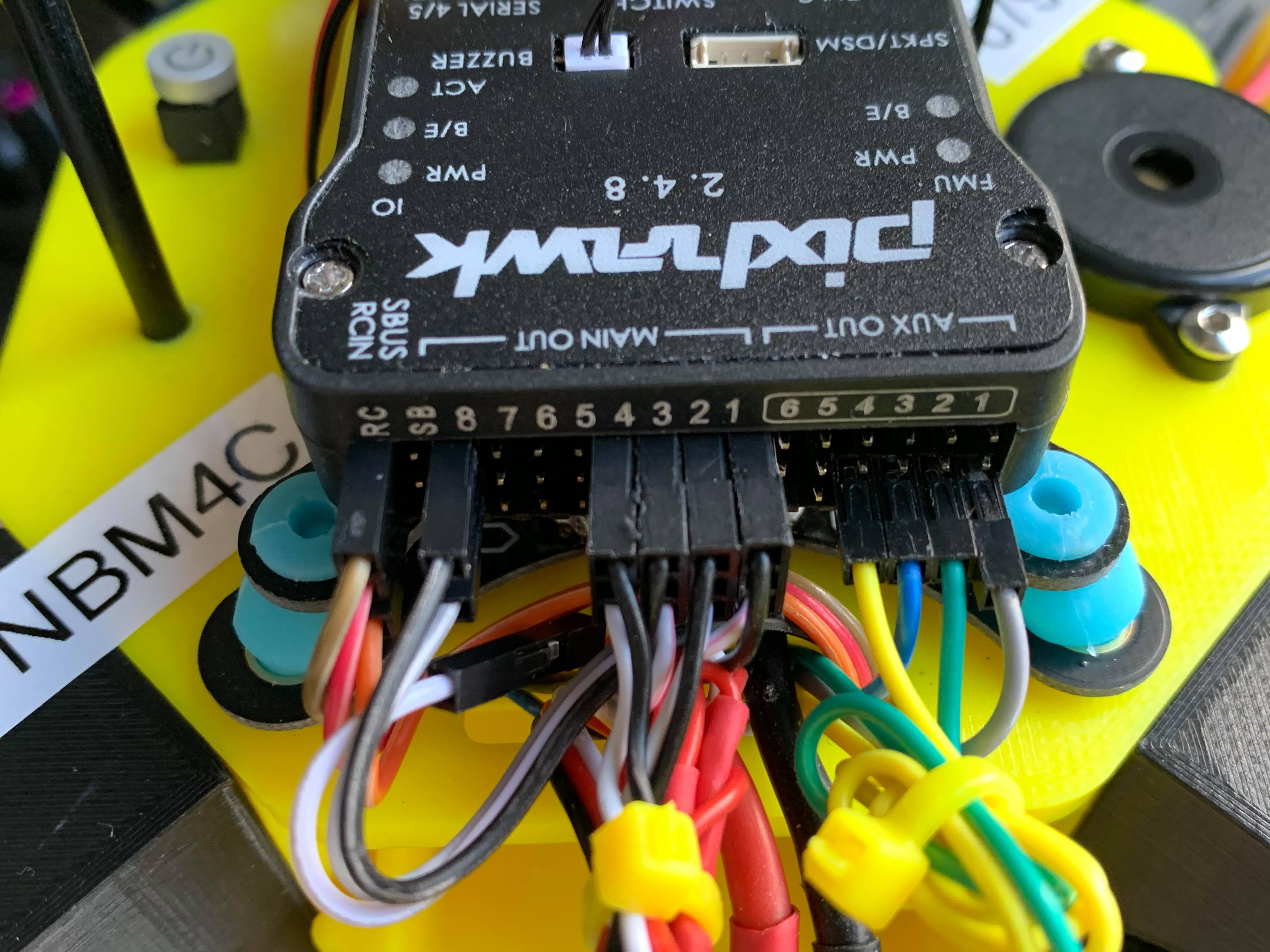
Okay great! So here is how I’ve got everything now connected.
MAIN 1-4: ESCs (signal + ground)
8: Gimbal (signal + ground)
RC: Radio receiver (independant power supply from Pixhawk) (signal + ground + power)
AUX 1-4: LED strips (each with their own power and ground from the associated ESC) (signal)
Will hopefully test some point at the weekend when the new GPS arrives, thank you massively for all your help! Hope to give back to this community at some point everyones incredibly helpful.
Okay so interestingly I connected it to a Lipo as shown above and ESCs beeped and Pixhawk looked to be booting.
Then I disconnected and reconnected and, once again, I heard a pop followed by smoke coming from what I assume is the same capacitor. Seems like it has to be something else… Seems coincidental that the second power up after reconnecting my LED strips it would pop again. I have powered it up by Lipo many many times today before this point.
As suspected, that same capacitor has blown. Unfortunately not sure I have learnt much from this popping. Time to see if I can ressurect this Pixhawk for a second time…