" AUX OUT 5 and 6 cannot be used by default because they are setup as [Relays]
These pins can changed to Servo outputs by setting the [BRD_PWM_COUNT] parameter to 6 and setting RELAY_PIN and to RELAY_PIN2 to -1.
The RELAYPIN represents Aux 1, and RELAY_PIN2 represents Aux 2.
Is this a typo?
If we want Aux 5 and 6 to be PWM, shouldn’t we be changing RELAY_PIN5 and RELAY_PIN6 to -1?
Also, RELAY_PIN values such as;
49
BB Blue GP0 pin 4
50
AUXOUT1
51
AUXOUT2
52
AUXOUT3
53
AUXOUT4
54
AUXOUT5
55
AUXOUT6
57
BB Blue GP0 pin 3
113
BB Blue GP0 pin 6
116
BB Blue GP0 pin 5
What do they really mean in terms of effect on Aux Pins? so if I set e.g. RELAY_PIN2 to 55, what will it do? And what in the world is BB Blue GP0?
Where are you seeing that statement “The RELAYPIN represents Aux 1, and RELAY_PIN2 represents Aux 2”? BB Blue is for Beagle Bone Blue boards.
Also, I believe I misspoke about the use of Main outputs for GPIO. With Copter this is true but for Plane and Rover where the Servo rate is low I believe you can use them.
Relay’s can be configured to any Aux output it’s not fixed as your 1st table would seem to indicate. So, if you select RELAY_PIN2 to 55 Then Relay 2 will produce output on Aux chan 6. The numbers are the pins on the processor associated with the outputs.
So let’s say you want to use RC chan 7 to activate Relay 2 on Aux output 6. Then
RC7_OPTION (34)
RELAY2_PIN (55)
Maybe you should re write Ardu pilot documentation. Some concepts are poorly explained.
So, I would re write the relationship this way;
Definition: Any channel on the Transmitter (Tx) can act as relay "trigger " function “or” for any other available features inside PixHawk FC. To accomplish this, it requires few steps to build the relationship between the Tx and Pixhawk output Aux Port pins (Actual Pins).
Step 1: Inside the Tx assign e.g. Channel $ ( where $ is 1 to available number of channels) to Logical Auxiliary Output port n (1 to 6) which you want to behave as a Relay. e.g. Tx CHAN 7 = AUXOUT2. This doesn’t mean at this point that Aux Pin 2 will act as Relay output inside the PixHawk. All we have done is we told the Tx to send PWM relay signal to PixHawk FC using AUXOUT2 channel.
Step 2: Next, set RC$_Option =34 via mission planner, where $ is the channel number selected inside the Tx (e.g. 7) and 34 tells mission planner that signal coming from the Tx CHAN 7 should be used as relay signal. Now PixHawk knows that any signal coming from Chan 7 should be considered as Relay signal but next we need to tell PixHawk which of the Aux output Pins should act as Relay pin.
Step 3: The Aux port assigned inside the Tx and which Actual out put Aux pin on the Pixhawk act as relay is done via one single parameter change. To accomplish that, use;
RELAY_PINz = Value
Where z = The actual Aux Pin (1 to 6) in the Pixhawk.
Value = Is what defines which Aux port has been used on the Tx to send the signal.
Value = 50 =>AUXOUT1 = RC9 inside your radio.
Value = 51 =>AUXOUT2 = RC10 inside your radio.
Value = 52 =>AUXOUT3 = RC11 inside your radio.
Value = 53 =>AUXOUT4 = RC12 inside your radio.
Value = 54 =>AUXOUT5 = RC13 inside your radio.
Value = 55 =>AUXOUT6 = RC14 inside your radio.
You have it all wrong. In your example above if you set RC13_OPTION to 66 you would activate Relay 5 on Aux channel 5. If you changed RELAY_PIN5 to 55 output would be on Aux 6. In your next example if you are seeing output of 1.23V it’s not working.
You are confusing inputs with outputs. Aux channels are not directly associated with RC Inputs and Relays are not directly associated with Aux channels. You have to assign those associations with parameters.
Just follow the logic with your example corrected.
RC input channel 13 has been set to activate Relay5 (RC13_OPTION=66)
Relay5 has been set to output on Aux channel 5 (RELAY_PIN5=54)
On a Pixhawk:
Aux Output 1= Output Chan 9= Processor Pin 50
Aux Output 2=Output Chan 10= Processor Pin 51
and so on.
RC input channel 13 has been set to activate Relay5 (RC13_OPTION=66)
Relay5 has been set to output on Aux channel 5 (RELAY_PIN5=54)
and when I measure the voltage between GND and Signal pin, it goes up to 1.232 volts, not 3.x. It could be because the volt meter is not providing sufficient load?
In Summary, I guess this is what you are saying.
Variable x= Channel number used inside the Tx. It could be any channel from 1 to 16 (If using 16 Channel Rx)
RCx_OPTION = Relay Value
Relay Values are;
28 for Relay 1
34 for Relay 2
35 for Relay 3
36 for Relay 4
66 for Relay 5
67 for Relay 6
Next;
Relay_PINx =
50 => Aux Out Pin 1 will act as Relay
51 => Aux Out Pin 2 will act as Relay
52 => Aux Out Pin 3 will act as Relay
53 => Aux Out Pin 4 will act as Relay
54 => Aux Out Pin 5 will act as Relay
55 => Aux Out Pin 6 will act as Relay
The output doesn’t need a load. I have the exact configuration on a bench Pixhawk and as expected Aux out 5 outputs 3.3V when the assigned Tx switch is activated. SH in this case as per your example.
No, if you use MissionPlanner to download log files (over mavlink) it automatically creates a param file and others
Or
you can go into Full Parameter List or Full Parameter Tree and on the right, save to file
That configuration should work. On my bench Pixhawk it does. Some basic troubleshooting:
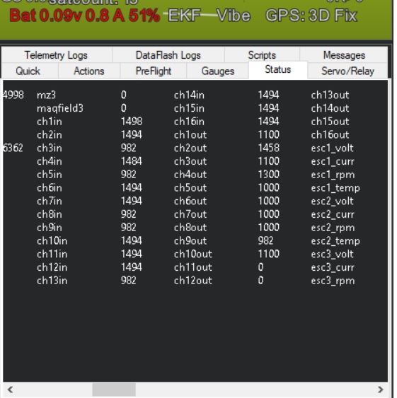
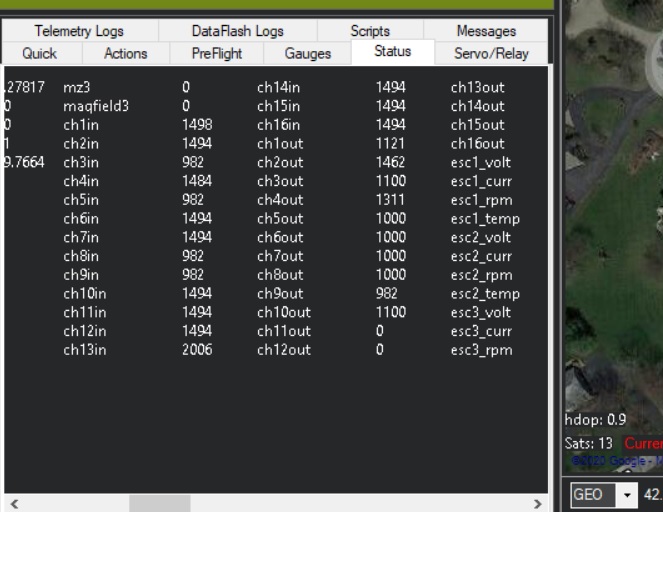
Does Ch13 go >1800µs when you activate the Tx switch you have assigned?
The values that are shown on the screen are in µs is what I mean. Basic RC stuff. Your Ch13 In is activated and showing 2006µs which should trigger the relay output (it’s over 1800µs). I don’t know what else to suggest it’s working for me.
dkemxr
maybe I have a bad voltmeter? let me figure it out.
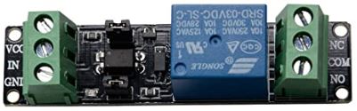
Can you directly connect a 3V relay to the pin or do I need a small circuit using a transistor?
I tried the following:
Connected an LED between GND and Signal Pin. LED can turn on @ 1.5V. So it lights up when I flip the switch.
Interestingly, while the LED is connected and if I also connect a voltmeter I get still 1.232 Volts and LED doesn’t light up. How much current Aux Pins can draw?
I have a single ESC BEC (Prop motor) powering one of the Main Out Pins…
 Maybe you should re write Ardu pilot documentation. Some concepts are poorly explained.