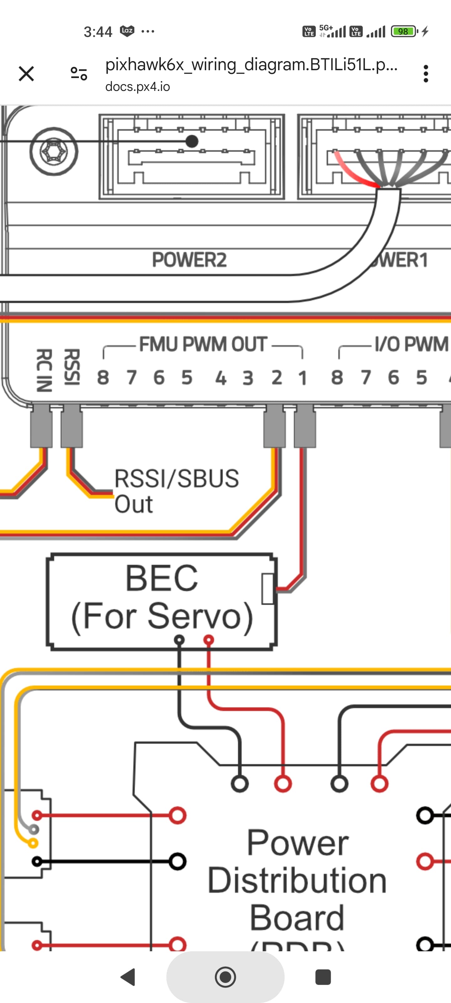
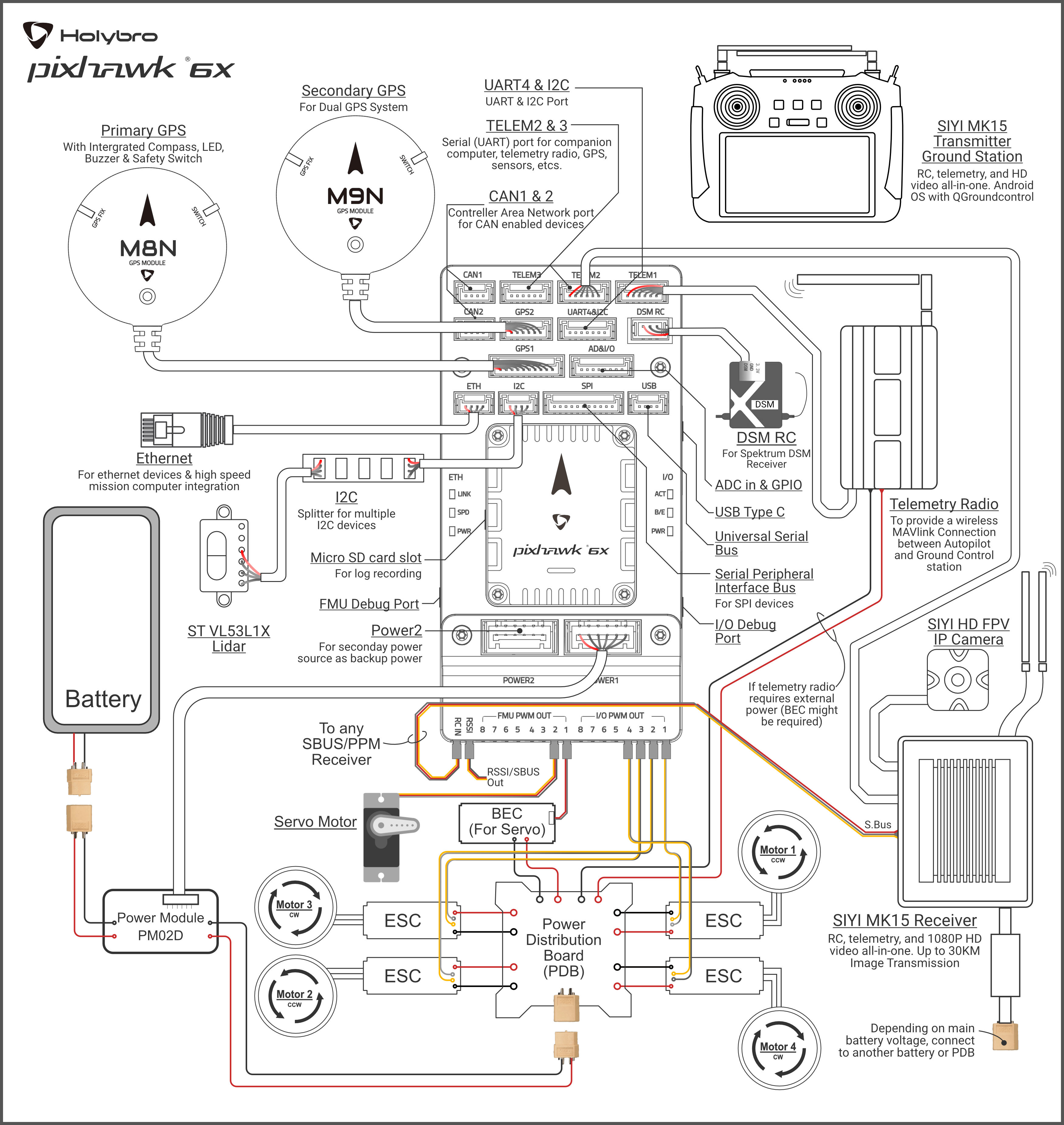
I’m building a Rover using a Pixhawk 6x and need to control 4 relays. I have everything set up in the config correctly, installed a BEC on the servo rail and when I press the button on the controller the signal outputs about ~3.3v on the line. The relays are 3.0 / 3.3V activating, which should work with the Pixhawk.
The relay has an optocoupler and I have isolated the power so all the Pixhawk needs to do is light up a few mA IR LED inside the optocoupler to trigger the relay.
When triggered via the controller, an indicator LED on the relay lights up. The relay however does not trip. Does the Pixhawk not have enough current? This should be less than 10 mA of current and the STM documentation says the IO pins should be capable of sinking and sourcing 20 mA.
I have tested the relays with an external power supply set to 3.3v and it triggers without issue. The current draw also doesn’t seem to be very high on the trigger signal, again a few mA.
Here is a photo from before I isolated the power. The relay itself is powered from a separate supply so it does not depend on the Pixhawk servo rail to provide the ~80 mA required to drive the relay magnet.
If there’s no common ground, there’s no way for it to work. Check that there’s continuity between the autopilot ground and the ground pin on the logic side. If it’s open, you need to fix that, first.
I use relay boards similar to this one often. They work well.
I believe you are correct. I tried tying the grounds together and it didn’t change anything. I used my multimeter to test continuity and that joined the grounds and they triggered. It may have been a break in the connection. I’m now rebuilding the relays into a new case and will report back.
Built a new set of 4 relays. Made sure the grounds were connected. Isolated the coil power supply. Tested with the FC. Nothing.
Voltage still reads 3.2v and 0.02v when button is pressed and released.
Tested with a 3.3v power supply on the trigger line (no FC connected) and it works as expected. Grounds have continuity.
No idea.
I would swap everything over for 5V, but while the Pixhawk 6X from Holybro says it’s just an easy resistor change there is zero documentation for it. I should have gone with an Orange Cube+ with the built in voltage select in the software.
FC servo output signal pin is connected to the relay module optocoupler input?
FC servo output GND pin is connected to the relay module optocoupler GND pin?
Both connections have been tested with an ohmmeter and are low-resistance (milliohm range)?
The relay module itself is supplied with its own voltage greater than 3.3V?
The voltage 3.2V or 0.2V is measured directly at the optocoupler input, optocoupler input against the common GND of FC and optocoupler?
Do you have an adjustable DC power supply that you can connect to the optocoupler instead of the FC? If so, slowly increase the voltage there from 0V to 3.2V, at what input voltage does the relay switch?
0.1 Ohm / 100 mΩ. That’s as low as the multimeter I have handy will go.
It has a variable power supply that is currently set around 3.3-3.4V. The relays are 3.3V rated.
Yes.
Yes. The trigger is at ~2.7V.
I can’t get too far into it without disassembling everything. The jumpers on the relay boards were soldered from behind to ensure the grounds are connected on both sides of the optocouplers. Then I ran jumpers between each relay board for redundancy. The grounds are connected in multiple places just to make sure. The 3.3V external power supply is only on the coil side, there is a separate 3.3V supply at the Servo rail.
That is actually a bit mystical. Based on the electrical connections and measurements alone, I can’t see any reason why it wouldn’t work.
Can you measure the input current at the control input if you
control the relay module with your controllable power supply at 3.2V input voltage
and the same measurement if the relay module is controlled by the FC.
I’m taking everything apart and under no load, the Pixhawk is putting out 3.2-3.22V. When connected to the relay, it must be drawing so much current that it only measures 2.69V… and ~2.70V is needed to trigger the relay.
This kind of makes sense since there is a 100ohm resistor in line with the optocoupler, limiting current to 30mA, where the Pixhawk can supply 20mA. That resistor should probably be 200 or 300 ohm instead.
I’ll be getting the new 4ch relay board in a few days and will completely rebuild it and then try again. My guess is these relay modules are just bad.
In your case, how do you supply the power source? What type of BEC that cannot even support 30mA? Which pin from Holybro Pixhawk 6X did you connect to the relay?
How comes this new result.
This was my question before and you stated two times that the input voltage from FC to the optocoppler on optocoppler side was 3.2 V
How can anyone help if you don’t answer correctly the questions. We are not sitting beside you and can wathch what you do.
As stated, BEC is capable of 3 amps. That being said, I tested with the BEC connected and the BEC disconnected. The 3.2V is present at the signal pin regardless of the BEC. You do not need it for the control signal, you only need it if you are powering a device. It’s not relevant from what I can tell. If there were any schematics for the Holybro Pixhawk 6X it would be clearer.
Holybro / Pixhawk doesn’t even state how much current the pin is able to supply. OrangeCube states it in their documents for their product. One of the reasons why I should have gone with the OrangeCube.
The board is wired correctly with ground connected to ground and the signal pin connected to the trigger pin on the optocoupler. Power from the BEC / servo rail isn’t needed as there is a separate power supply on the relay side of the optocoupler. I’ve got them on AUX1 - AUX4 of the Holybro Pixhawk 6X.
I answer questions correctly, but I can’t answer every question as I do not have a full suite of ammeters, test probes and multiple hands to hold everything. There is a lack of documentation on the Holybro Pixhawk 6X and for the relay.
None of this relay makes electrical sense. I did not need to connect the grounds across the optocoupler, that defeats the purpose of the optocoupler. I did because multiple people said it needed to be done. The optocoupler should have triggered with 10mA, but it in theory is drawing far more.
My solution will be to replace the relay board with the version that has multiple FETs to trigger with much lower current (around 5mA). If it’s still not working then the Pixhawk 6x is defective with these signals. I would need to connect a resistor to the Pixhawk and ammeter to know how much current the board is capable of supplying.
I think the bottom line is that nearly all of these autopilots have a very low current capacity on the GPIO pins, and @geofrancis has experienced the same with relay boards of similar design. It stands to reason that a different relay board is likely the best course of action.


