Please don’t do this if you don’t want to destroy your Pixhawk.
All FCs are the main core the common and these STM controller can deliver upto 20mA per pin. On many of the small size FC the pins are directly used as output of the board with no driver stage in between. Maximum if it is a good one a limiting serial resistor. So if you test your Pixhawk with a a to small resistor to GND it can be damaged on the output pin of the STM controller itself which destroys your Pixhawk. HW defects can’t be replaced by SW reset :-))
So if you always not more than maximum 20mA you are moreless on safe side independ of the model of your FC.
This simple relay boards are not only made for our FC. They are made for any kind of small and cheap controller systems and they switch some times different independent power sources. Therefore the optocoppler makes sence. In our case as we most use only one battery for all you are right the optocoppler makes not so much sence in point of electrical isolation.
20mA max, 8mA recommended (for most boards).
Oh yes, you are fully right. The 20mA is only the absolute maximum current for one pin itself.
But if more than one pin consumes this high current than as next we reach other limits also. Therefore is the recommendation of 8mA a good practice
Have you try placing the relay module near the Pixhawk 6x and use a shorter wire, say 5 cm. Remember, your wire carry ohms.
Here is a new and unfortunate discovery. During boot and for appropriately 3-5 seconds all AUX pins are HIGH. That means all relays are going to be energized for several seconds upon boot. That’s a terrible problem.
I have read many forum posts about the topic and adding additional hardware safety interlocks is not a good solution. This has to be a software thing causing the pins to become outputs before the software loads and actually knows what the pins need to be. I’ve read that this is considered to be a safety feature in case something depending on a PWM signal interprets a 0v signal as a valid pulse to run a motor? That should not be how any PWM device works. This is 100% a software decision to set the pins to outputs and high at boot. The pins should be floating inputs at boot and only become outputs once the software loads and it knows how to assign the pins and what the default state is.
Have you give Main out pin a try?
Kindly share the following parameters
RCx_OPTION
RELAYx_FUNCTION
RELAYx_DEFAULT
RELAYx_PIN
SERVOx_FUNCTION
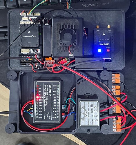
New relay module works! This one has no optocouplers and instead uses a pair of NPN transistors that allows it to trigger on like 1mA. This is also now 24VDC powered, so no need to worry about trying to trigger a relay on 3.3V.
I swapped the signal pins from AUX1-4 to MAIN5-8. Now the on blip during boot is a fraction of a second and should not affect anything. I would still highly recommend the devs leave the AUX pins as input / high impedance until the system boots and it knows the default state of the pin.
I’m pulling together a V2 of my Rover - I like the layout of your gear and the use of the Wago connectors. Any chance you can share your schematic? Shape files for 3d printing?
Nice work!
I certainly can, but unless you’re using the exact same products and the same use case for the relays it won’t be super beneficial. The relays control my ICE engine and raising and lowering a platform.
There are a ton of modular wago files available if that’s the only thing you’re after: Search models | Printables.com
perfect - never came across these, but, never searched for the Wago gear specifically - thanks a ton. . .cd
