Unfortunately I get only ca. 600m range… very far from 2.2km… Can you, please, advise on how I can improve the positions of my antennas (and maybe other tips) to get the 2km range?
What’s your vtx power set to? What kind of antennas to you have on your receiver? Do your antennas all have the same polarization? Are you using a patch antenna or just DI-poles?
Did you manually tune the frequency on your goggles or did you use Auto-tune. (Some vtx Channels are close and some auto tunes will actually select the wrong channel because it’ll close enough…)
I can not identify clearly where the antennas are positioned, but you should stay away from carbon. It acts like a shielding.
Thus, orientiert the antennas perpendicular to the arms. For receivers with only one antenna this might create a blind spot if the antenna is pointing directly to you. But in practice the 900 mhz RC signal is always stronger as the VTX link.
I didn’t mention it explicitly, but my problem is with the radio control signal (RX <-> TX), not with the video signal. It’s sounds strange but I loose control while I still have good video signal.
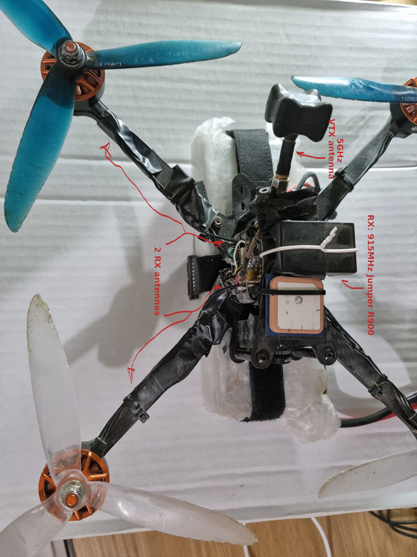
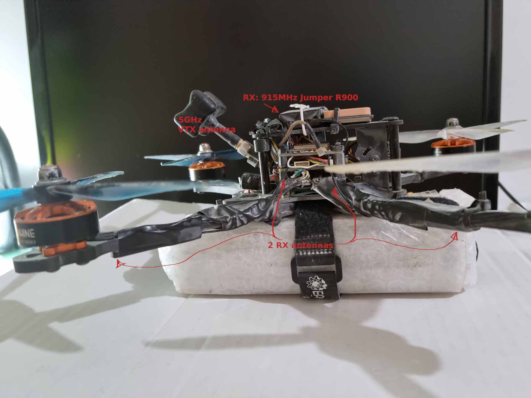
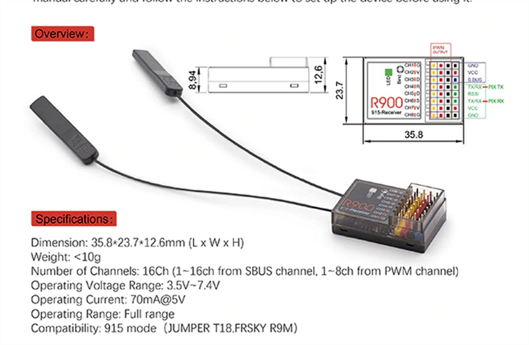
The VTX is set to the maximal power of 600mW and works quite well. I’m sorry, but I don’t know whether both antennas of the Jumper R900 915MHZ receiver has same polarization or not, but they do look symmetrical. Can you estimate by the picture in the link above whether they are patch antennas or DI-poles (I don’t know what’s that)?..
Frequency on the goggles was chosen in auto-tune… but I don’t have problems with video, but rather with control… Can video signal on 5GHz interfere with the 915MHz control signal?..
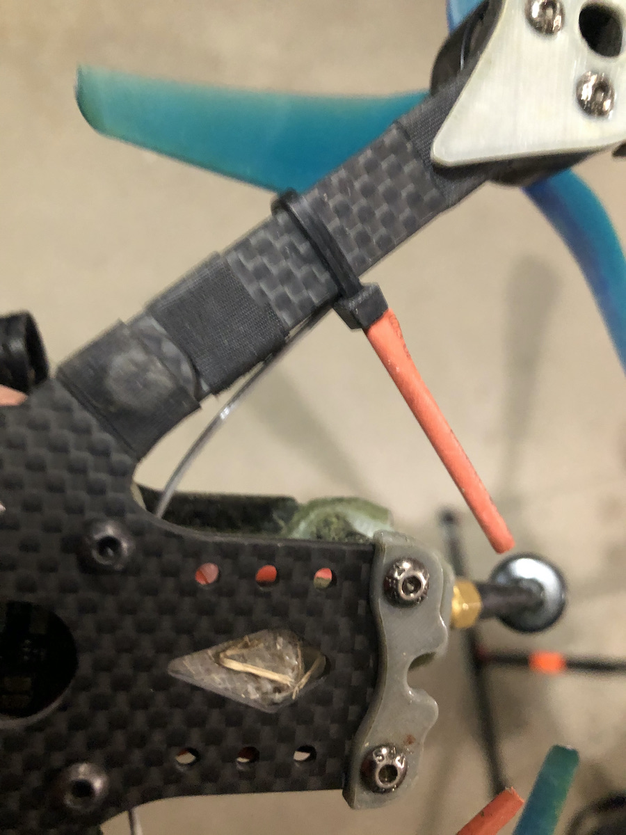
On my picture both antennas of the receiver are positioned below the carbon arms (tightened with the black insulating tape). To better identify them on my foto you’ll probably first have to see them detached:
I’ll remove them from the arms as per your advice. May I attach the two antennas to the battery? Will this not act as shielding? As you can see on the foto my battery is wrapped with bubble wrap… so in practice there will be a 5-7mm layer of air/plastic between the battery and the antennas…
Looking at your configuration I can see why your range is limited. I bet your antenna is getting saturated with noise from the flight controller and esc. I get around 3km with a standard FrSky
X8R… never mind the crazy range you can get with 915mhz. I’m flying fixed wings most of the time.
I make a rf shield out of thin cardboard and copper foil and run a ground to it. It goes over the Flight controller and ESC. I’ll use my 2.4Ghz setup as an example… the pcb antennas are on the outside of the airplane fuselage with a nicely cut piece of black gaff tape over them, the bluetooth downlink is also located away from everyhing on the feft bottom of the interior portion of the fuselage because I just use it for local configuration updates, calibration, and to upload waypoints.
The GPS is in top, another pieve of thin cardboard with copper foil on the bottom, BN-220 on top, fuselage cover over it.
The telemetry range of the 933mhz setup is not ideal. telemetry cuts out at 1km. I have control out further than that. The old 2.4ghz FrSky telemetry is more dependable. I’m waiting for another firmware update for the jumper multiprotocol module, hopefully telemetry range is fixed.
I think if you clean up your wiring, add some rf shielding around the flightcontroller, remove all that electrical tape where your antennas are, clean that up. use zip ties and gaff tape on the antennas, not electrical tape. You are reducing the signal that way. I bet your range will increase. Compare the rssi level from what you have now to what you will have after the changes I suggested, and post them!
Black insulating tape around antennas… you are reducing the rf signal! If you want to cover it use gagging tape, and don’t use multiple layers like that… one layer! Plastic and paper are insulators.
After work I will post images of my avionic work… My mini AR Wing with Sparky 2.0 FC and BN-220 get’s 24 a 24 sat 3d lock at my field. Before the RF shielding I was lucky if I got 6 SATS. Also the GPS is located inside the aircraft… not on top. The key is RF shielding… maximize a clean signal to your control and telemetry antennas. Good Luck.
If I wrap the carbon arms with aluminum foil first, and only then attach antennas to it will solve the problem of shielding?
Pay attention, that both antennas are located bellow the arms, so there is direct line between the transmitter and them… (there is no carbon in between)… is it still problematic? I.e. is there such thing as shielding from above?
The only other place to put the antennas is the on the battery’s vertical side plane. However the battery itself is wrapped with plastic… So it also probably will act as shielding, correct?
I plan to to cut a plastic bottle and place it around the electronics (FC, ESC)… Will it be enough to isolate the electronics?
Being below the arms isn’t as bad as being on top but it’s still bad. I know a lot of people do this but they should consider themselves lucky if the radio still works well.
Many radios use metal which is not physically connected to main part of the antenna to boost the signal. This extra metal (or carbon) needs to be just the right size and in just the right location to boost the signal or otherwise you’re likely to make the signal much worse.
The batteries would likely also shield the batteries but it might not be as bad as the carbon.
Ideally you want some sort of plastic or wood rod to hold the antenna away from the rest of the quad. I’ll try to find some photos of good examples and post them here.
Looks like I’m a little late to the party, but the other’s have got you covered. You need to fix that antenna placement. Along the carbon arms is killing any reception you have.
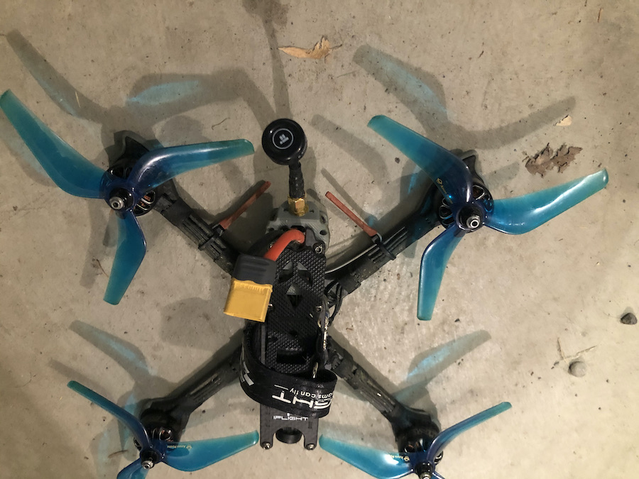
The pictures below aren’t exactly the same, but it’s one of my 5" quads. I run the antenna leads along the arm and then turn them out from the arm. I face the leads pointing in the same direction as the prop is spinning so they don’t get cut in a crash. To hold the floppy wires around I use zip tie and some heat shrink. Simple and it works well.
Make sure the two antennas are at least 90 degrees from each other. If you want best performance with 900MHz they should be pointed straight up and down, and make sure the antenna on your radio is also pointed vertically. (The quad in the picture is on 2.4Ghz Spektrum, but for my FPV gear that gives me more range than I want to walk after I crash into something)
This gives the max range beside orienting them vertically which would be much more effective but is however unpractical for the transport of the quad and the antennas are be prone to damage. It is a R9slim+ receiver with two antennas.
Range is several km, telemetry is limited as the power of the receiver sending back information is limited in power.
I must admit I’m not that good at physics… could you, please, explain
what is the problem with the insulating tape? It’s like plastic so it doesn’t acts as shielding… metals do… am I right? As you can see on the manufacturer’s picture of the receiver - the ends of the antennas have some plastic cases on them… so it looks like plastic should not be a problem? Am I wrong?
I don’t have neither RSSI nor telemetry in this particular drone (I was not that good at soldering and damaged some pads), but I’ll post here how my range has changed after adopting all the useful advises here.
What is the difference between the insulating tape and gaffer tape in regards of antennas’ signal strengh?
What is this plastic or silicon cover of the electornics? Is this meant to shield the radio noise emitted by them or just for mechanic protection? Shouldn’t it have some sort of metal layer to be able to shield the internal radio noise?
Does this mean that carbon acts as a metal? Strange, my chemical intuition said to me it should behave more like a plastic (as carbon is present in all plastics)…
If you want best performance with 900MHz they should be pointed straight up and down
Does this mean that both antennas should be positioned vertically but one points “up” and one “down”? Or can both be positioned vertically and point down towards ground? In both cases - antennas are parallel to each other so how can one apply this “Make sure the two antennas are at least 90 degrees from each other”?
Let me put it this way… Take your quad outside, the way it is…turn it on, turn on your transmitter, go to your transmitters screen that displays rssi, walk about 50m away from the Quad, take note of the rssi value. Go back to your quad, remove all the electrical tape from your antenna, repeat checking rssi.
The rssi value read with the electrical tape off will be much better. Electrical tape is not 100% rf transparent. You are reducing signal strength with all that tape. Not blocking the signal, electrical tape is not an rf insulator, if it was you will get no signal. You are attenuating the signal.
If you want the best signal possible just use zip ties, no tape