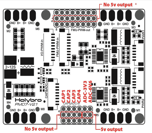
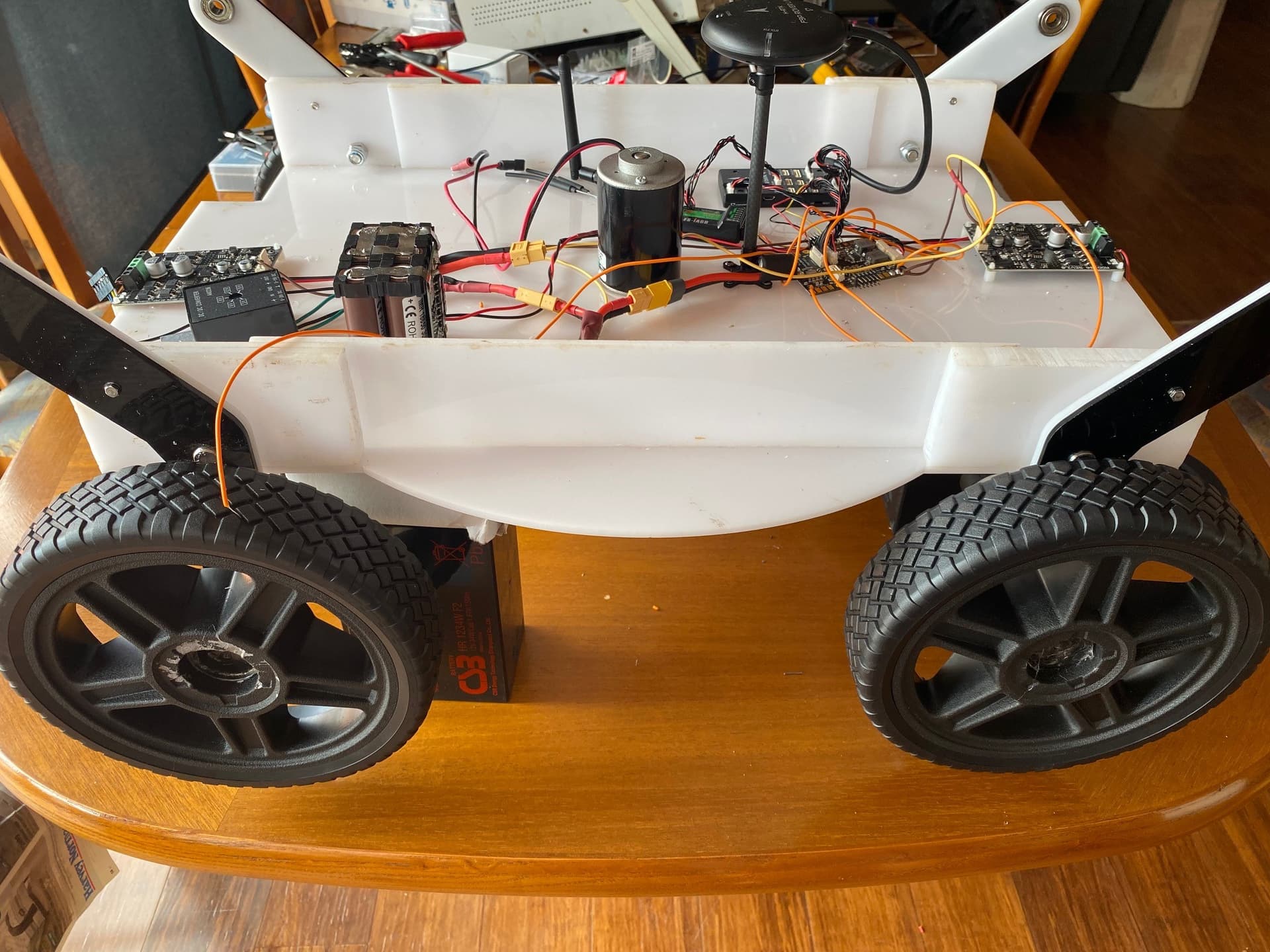
Configuration: Skid steer rover. Hardware: Holybro Pixhawk 4 with PM07, F9P GPS and telemetry radio. MDD10A Motor controllers. While I can see the radio control six channels in Mission control and QGround control calibration moving the joysticks has no effect. For Servo Output Channels 1 & 3 set to throttle left and throttle right respectively. There is only a PWM signal on M1 and M3 on the PM07. When turning on the power to the Pixhawk 4 nothing happens until the switch is pressed, at which time two wheels start turning. There is no control over the wheels. Please could I have some assistance with this?
A few more details about your rover, pictures perhaps and a parameter file would be helpful.
Some guesses:
If you have more than two controllers, you have to configure additional outputs or use y-cables.
If the motors start turning with neutral output, it is a calibration and/or a deadzone issue.
Stick to Missionplanner for setup and tuning. Qgroundcontrol is missing a few useful features.
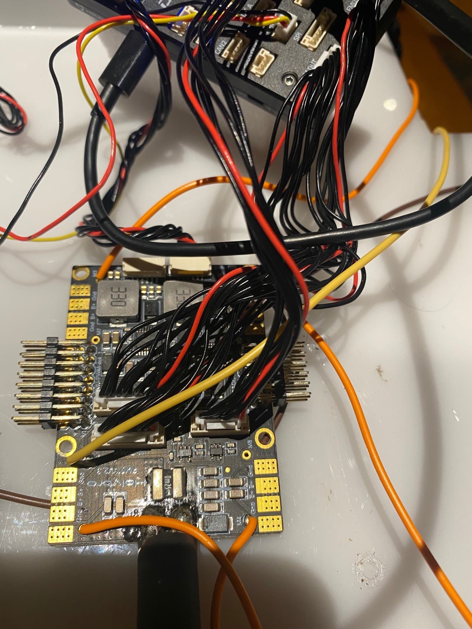
Thank you for your response. Attached are the parameter file and pics. Each motor controller controls two motors (two controllers per controller board with two PWM inputs each). The PM07 actually has a place to connect 8 ESCs (M1 to M8) and in a quadcopter configuration, 4 of these are connected to ESCs. The way I have it configured the Pixhawk is only sending PWM signals to M1 & M3. I need to: 1)find out how to change this, 2)find out how to control the motors with the RC. (FS-16X radio) Ignore the motor in the middle for the meantime. I will come to that later.
Mower-motor drivers-GPS.param (14.5 KB)
Hi,
after a first look, I noticed very strange output values for output 1 and 3. Both have a minimum of 500us, a trim of 800us and a max of 1900. The defaults would be 1100, 1500, 1900. If your motor controllers work in the RC PWM range, the default values will be the best to start with.
I also noticed the RC trim for the throttle channel (RC3) is equal to the minimum value. Missionplanner tells you to put the throttle to its minimum at the end of RC calibration, but that is actually wrong for rovers with forward/reverse ESCs. The throttle stick should be in the middle position. If you have a sticky throttle stick (not self centering), you can either activate the spring for it, if your transmitter allows you to do that, or swap the RC channels for pitch and throttle with Missionplanner. Search for the RCMAP_PITCH and RCMAP_THROTTLE parameters in the “full parameter list” and exchange there values.
Redo the RC_calibration.
The motor controllers are perhaps not the best for this application. They have two modes of operation, sign-magnitude mode and locked anti-phase mode. I am trying to use them in locked anti-phase mode. This means that the motors will turn in one direction when the PWM duty cycle is >50% and in the other direction if the PWM duty cycle is <50%. At 50% the motors should not turn either way. The reason I am using this mode is because sign-magnitude mode requires two inputs, PWM and Dir. Since the Pixhawk 4 only outputs PWM I cannot use this mode. Are these motor controllers good enough or can you suggest something else? I am using 12V motors that draw 5 Amp at stall. I have made the changes you suggested with no change in behaviour. I will attch the new parameter file.
Mower-motor drivers-GPS-01.param (14.5 KB)
Ardurover has a controller type “brushed with relay” to support a DIR pin.
Have a look here:
https://ardupilot.org/rover/docs/common-brushed-motors.html
You will have to connect the Pixhawk 4 FMU outputs to the PM07, too.
Thank you. I have connected the motor controllers as Brushed with relay now. I still don’t see any “radio in” signals making corresponding changes to the Servo out signals. Please see attached pic.
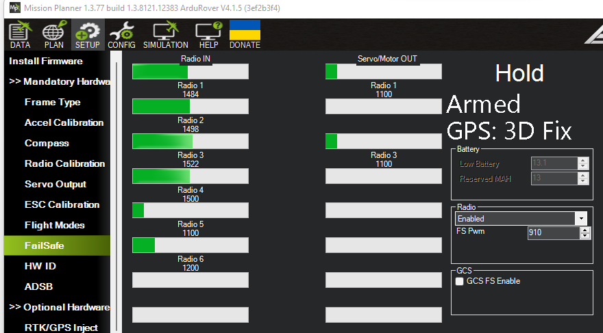
You are in “Hold” more, so no output is as it should be.
Please read here:
https://ardupilot.org/rover/docs/rover-control-modes.html
Switch to “Manual” mode and see if it changes anything.
Hi Sebastian. My Mode_Ch was set to channel 8 and was therefore not seeing the switch. I have now set it to 5 and this is working. I am still net getting anything for the Dir signal on the relay pins Aux 5 & 6 and motors are not turning. I have checked with an Osciliscope and the PWM signal is changing when I move the sticks on the radio so I think if I can get the relay signal through I will have a win.
Did you setup the relay pins according to this page?:
https://ardupilot.org/rover/docs/common-relay.html#common-relay
Hi Sebastian
You have been a great help and I really appreciate it, thank you!!. I had not read all the way through. I am now stuck with a problem where if the stick is in the middle position the motors do not turn. If I pull back or push forward on the stick, the motors turn in one direction, that same direction no matter which way I make the stick go. I am going to do some testing with known +5v and ground leads to see what happens…
This sounds like the relay pins are not working/not connected properly. If the DIR pin does not change state, the motors only run in one direction. Did you connect the additional mutiwired cable between FMU PWM OUT of the Pixhawk and the FMU PWM IN on the PM07?
Yes the PWM OUT cable is connected. You are right that relay pins are not working. I am trying to work out what I have done wrong. I am a little confused as to what I should select for the relay outputs. I am also confused about where to connect the Dir output on the PM07 board.
The FMU IO outputs are connected to the servo headers on the PM07. They should be labeled as FMU PWM OUT.
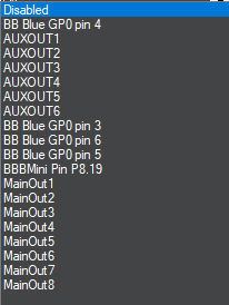
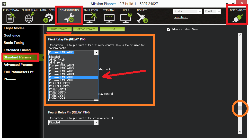
OK. I have hit a wall. The doco is not up to date and so I am not sure what to do. The documentation says “Pin designations for several different autopilots are shown in the drop-down box.” but this is not the case. The pin assignments list is as I showed in my previous post while the example given in the doco is as per the one I have included with this post. Also after configuring it as AUXOUT1 and AUXOUT2 the output does not change when moving the stick it does however change if I force it in on the data tab by clicking on high or low. 9 clicking high on 9 changes the output of FMU pin1, 10 changes FMU pin 2 etc. It does not however behave like a relay. The output is PWM on all pins.
Here is the ardupilot documentation for the Pixhawk 4:
I would also always the the full parameter list to setup the vehicle. That way you can be sure everything is entered where and as it should.
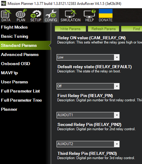
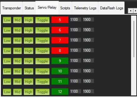
Thank you Sebastian. I have been able to work out some things but still unable to get the relay output on the Auxiliary PWM pins. My first problem was that I did not set the BRD_PWM_COUNT parameter to 4. This meant that all the PWM pins were allocated to PWM. I have now done this and can see that this has taken effect because I now get RCOut: PWM:1-12 whereas I was getting RCOut: PWM:1-16 on boot. I have attached LEDs to pins 5 & 6 so that I can see if the pin is 0v or 5v but never see it go to 5v. I am still not sure what to select for the Relay pins from the choices in the attached graphic. I have tried AUXOUT1 and 2 as well as MaiOut 1 & 2 but still see not output.Also I am unsure how to link this to the motor drive.
The BOARD_PWM_COUNT parameter counts the AUX outputs used for PWM, so setting it to 4 frees up AUX5 and 6 for GPIO/relay use.
AUX5 would be pin 54, AUX6 is pin 55. Use the full parameter list and search for “relay” enter 54 for Relay1 and 55 for Relay2.
A wire from the output for AUX5 to the left motor controllers DIR pin and another one from AUX6 to the right motor controllers DIR pin is all you need.
That’s because on most boards the relay out voltage is 3.3V
Hi Sebastian
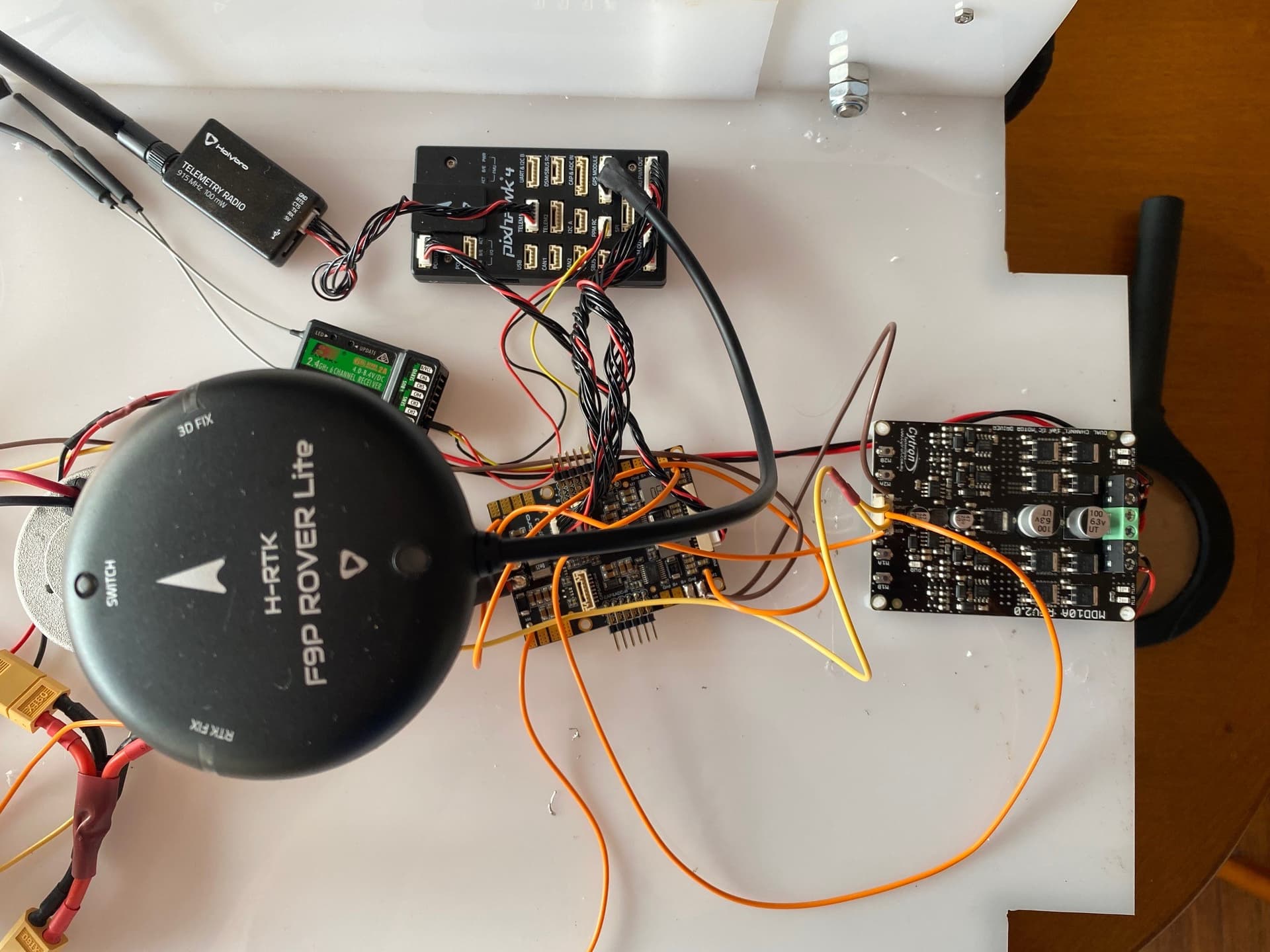
The Pixhawk 4 that I have does not have any pins on it for FMU PWM they are all located on the PM07. I am quite sure that I am correctly connected to them. I am connected to Pins S5 and S6 on the FMU-PWM-out pins. I am also supplying 5V to the 5V line. Those two outputs remain low (0v) even if I have manually made them High. (See graphics)