Omnibus F4 V5 & V6 Setup - Application Race Quad

Hi all,

I have spent some time now working to set up copter on my 250 race quad. It has left me scratching my head for a while but I have finally got things working. So I wanted to take this opportunity to share what I have learnt so far and I hope others will be able kind enough to correct me where I have made mistakes so that I can learn more.

Setup:
FC: Omnibus F4 V5 (not the pro version) running a daily build of 3.6.0 from 3rd Aug 2018
Reciever: FrSky XM+ micro receiver using SBUS
PDB: Mateksys HUBOSD8-SE
FPV: RunCam Sparrow camera, RC Immersion Tramp VTX, using onboard (onboard the omnibus that is) OSD.
GPS: Beitian BN-880 GPS

I used the instructions on the wiki to flash the boot loader and copter onto the board. I have had limited success with this method. It only worked about 1 in 5 times. I have found that flashing the firmware via beta flight (as described here) works every time. I originally flashed 3.6.0-rc7 and it worked fine including writing logs to the sd card. The only trouble is that the on-board OSD wouldn’t work. I subsequently found that the daily build from 3rd Aug 2018 works well, with both osd and data flash logs working!

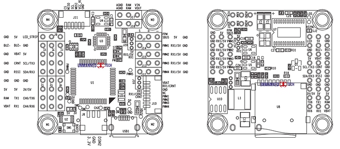
Please not that on the Omnibus F4 setup guide on the wiki it talks about jumping solder pads or removing resistors to select between SBUS and PPM receiver protocols. This is certainly true for the V2 and V3 F4 boards. It is not required for the V5 board. Simply solder your receiver to J7, on the attached pinout, and arducopter will automatically detect which protocol your receiver is using. Very neat!

As this isn’t the pro version of the board it doesn’t have a current sensor. There is however a current sensor on the PDB. I connected the ‘GND’ and ‘Curr’ outputs from the PDB to the ‘GND’ and ‘CRNT’ pins on J5 and J4 respectively. I am also powering the board with battery voltage via the ‘VBAT’ pin on J4. This gives me battery voltage and current on my OSD which I have found very useful. Having now calibrated the voltage and current inputs in mission planner I am pleased to report that it is working reliably.

I am powering both my VTX and camera off of the 10V outputs on the PDB. The Video out from the camera is connected to ‘VIN’ on J17 and the video output is connected to the ‘VOUT’ on J18. I have also run a common ground from ‘AGND’ on J17 to the same ground on my PDB. I have copied this setup from the excellent blog on dronetest (here) under the section entitled ‘Connecting your FPV Gear’. What I have done slightly differently is I have run the audio output from the camera straight to the audio input on the VTX. This setup works well for using the on board OSD function that ardupilot now offers. I must say that the OSD in arducopter is fantastic. Highly customisable and loads of options for telemetry that you may or may not want to display. Thank you to the devs that have put this together!

GPS. Ahhhh the GPS. This one has plagued me for quite a while but I am pleased to say that I now have it working. Originally I was trying to connect an OP GPS with a UBLOX 7 chip that I got from Amazon. I tried everything to get it to work. I connected to Rx6/Tx6, I connected it to Rx1/Tx1. I made sure that I was connecting Rx->Tx and Tx->Rx. I even swapped the Rx and Tx pins on the GPS just in case the pin outs were incorrect. I switched on all of the serial ports (1 to 6) to be gps. I had another identical gps that I tired. But nothing! bupkiss! Mission planner always displayed ‘GPS: No GPS’. I combed the internet to try and find out what was going wrong. I finally stumbled across an article the mentioned that this gps is optimised for open pilot. So i tried a different gps that I had, the Beitian BN-880 GPS, and it worked first time! The relief!!! The GPS is now connected on Rx1/Tx1 which corresponds to UART1. In mission planner the serial port protocol is controlled via the parameter ‘SERIAL1_PROTOCOL’. Note that if you want to use either UART3 or UART6 for your GPS it will require you to do a little edit in the code and build the code yourself. Rx3/Tx3 on J4 are currently hard coded as an I2C port. To change this you will need to change those two pins to be UART pins. Rx6/Tx6 (for UART6) have been inverted and you will therefore have to change the pins to output high if you are using a gps on those outputs. This can all be done in path:\libraries\AP_HAL_ChibiOS\hwdef\omnibusf4pro\hwdef.dat. I have decided not to use the compass that is fitted to the BN-880 as I fear there will simply be too much EM interference on my race quad. I know that @iampete has been having issues with the compass on his race quad. So I hope to find a smaller GPS unit than the BN-880 to make my build a bit tidier.

My question to you all: Is there something I should be aware of when looking to get a GPS that will work with arducopter? I think that the reason the OP GPS with a UBLOX 7 chip doesn’t work is because of how the UART back end handles the buffering of the data (i.e. it doesn’t). Any advice here would be greatly received! :slight_smile:

Maiden and tuning: With my race quad being incredibly powerful the default rate PID did not work at all. This is precisely as @fnoop described in this thread. The P,I, and D values are tiny in comparison to the defaults. In fact they are lower than mission planner’s suggested range. To give you a feel for it, to get my quad flying i initially set all rate I and D values to zero and managed to get it flying with rate P values of 0.022 for pitch and roll. I have since been trying to use auto tune to improve the tune, with limited success so far. I am going to continue with trying to get the auto tune to work for now but I may have to resort to doing it the old fashion way to get a really tight tune.

Anyway, I hope that this information will provide useful to someone, who like me, has been banging their head against the wall trying to get this board to work. I will post updates and videos as I continue to make progress with this build.
8 Likes

I have been flying and tuning more and wanted to share my progress and learning so far:

I have been struggling to get auto tune to be successful in finding a good tune that results in a crisp feeling in acro mode. It is my race quad after all! I found that it was forever being blown around by even the lightest of winds. I would fly the quad way upwind let it drift past me and repeat. The trouble was I was burning through an entire 1400mAh battery without it succeeding in auto tune. To remedy this I wanted to try using a position hold auto tune. This uncovered a rather annoying issue. I could not switch into any gps enabled flight modes. It was consistently an EKF failsafe that would prevent me from switching. I didn’t have a compass installed at the time. I had been through and disabled the compass and magnetometer but the EKF wasn’t having any of it. I tried changing various parameters related to the compass, mag and EKF to see if any combination would work. For example, the thread here suggests that despite not having a compass MAG_ENABLE should be left enabled. Sadly in my case this did not work.

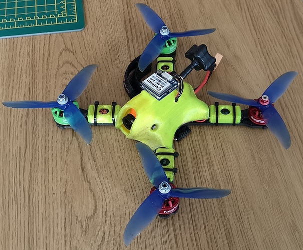
Having tried everything I could think of/find on the internet, I decided to add a compass to see if it remedied the problem. After a lot of faffing around I got the compass to work. It is connected to the available I2C port on the board (J1 on the pinout above). The compass was automatically detected straight away, with COMPASS_DEV_ID and COMPASS_EXTERNAL being filled in for me. However, for a while I couldn’t calibrate the compass. I tried Mission Planner, QGround Control, and Mavproxy and I was getting mav command 42424 errors. After digging through all of the parameters, pulling my hair out as i did, I finally found the issue: I needed to set COMPASS_USE = 1. Then all of the calibrations worked. I managed to get a ‘strict’ calibration using the live calibration function in MP. I also did a compass/motor compensation calibration. It was a little concerning as I was getting a max interference of 170%!! After all that I am very pleased to say that my quad will now switch to gps enabled flight modes. So I believe the issue to be related to the EKF fail safe routine. However, I am still doing some digging to find the source of the issue. With the very little real estate available on race quads and the EM interference that is almost impossible to avoid I am keen to get rid of the compass. Not to mention the poor aesthetics (I know, how vain!) of it being glued on top:

I have since been out to attempt an auto tune with position hold and it Works!!! I have been tuning one axis at a time. Using the position hold has significantly sped up the process, to the point that I can almost tune two axis on one battery. Having messed around in acro mode with the new tune it flies very well. It handles pretty much as well as it did when I was running beta flight.

As a learning opportunity I wanted to tune the quad with voltage scaling turned off. True to form, when ever I put a fresh battery in the quad would being oscillating and then settle down as the voltage dropped. I believe this is due to the auto tune finding the rate PIDs later into the battery and therefore at a lower voltage. I have now switched voltage scaling on and the quad consistently oscillates throughout the whole voltage range of the battery. So the next thing to do is start from fresh and complete a full auto tune with voltage scaling turned on. Back to the field!

5 Likes

Hi Matt, thanks for sharing this, was able te reproduce this on my F4 V5.1 and almost the same with F4 V3 AIO, except for this one I didn’t had to modify SERIAL1_PROTOCOL to GPS. Everyting seems ok. But one point, were you able to connect telemetry to TX6? Or another pin? Or maybe did you find another solution to get telemetry? Thanks. Chris

1 Like

Hi Chris. My pleasure, thanks for reading.

I haven’t connected wireless telemetry as of yet. I haven’t really got the space on my quad for it. I have been getting around this by using the onboard OSD on my FPV goggles or monitor. A sample of which can be seen here:
Mini Quad Throw Mode Trial

I currently don’t have anything connected on RX6/TX6. Have you been having issues using this port? Are you using SBUS on your receiver? I know that on Betaflight, if you use SBUS on these boards it occupies the UART6 Pins. However, I am not sure if that is true for ArduCopter.

I am also working on setting up ArduPlane on an Omnibus F4. I plan on installing telemetry on this. When I have had a go I can let you know how I get on.

Matt

1 Like

Yes, I’m using SBus. You should be right, RX6 TX6 could not be avaiable with SBus, but not sure… I was able to get frsky telemetry working on this board with iNav 1.9.1 using PWM6 as output using a patch. But had lot of troubles adjusting PID, so now I prefer everything on the same solution :wink: but hard to master!

1 Like

Looking at this post it has reminded me that hwdef.dat defines RX6/TX6 as having an inverter. That might be what is causing problems with your telemetry. You could confirm this by one off two ways. Either, comment out lines 86 and 87 in hwdef.dat:

PC8 SBUS_INVERT_RX OUTPUT LOW
PC9 SBUS_INVERT_TX OUTPUT LOW

and recompile the code. Or alternatively, you could temporarily move you telemetry to RX1/TX1. If that does just work then it is likely to be the inverter that is causing the issues.

1 Like

thanks, will try this, just waiting for my ttl 3232 to come, to build mi wire.

1 Like

thank you for this,great info ive still a bit to go to get it working

Hi Martin. No problem, I am glad it is of some use. Let me know if you get stuck or have any questions and I will do my best to help :slight_smile:

With the Omnibus F4 V6 having just come out I decided to get my hands on it and give it a try. I am pleased to say that the V6 board will work with the omnibusf4pro build of arducopter 3.6-dev. At the time of posting I believe I am correct in saying that with this version of the code you will only get 3 UARTS not the full 5 offered by this board. I notice that somebody has built a v6 nano version of copter. This still wont give all 5 UARTS. I am looking into trying to make a hwdef.dat file for the ‘full size’ version of the v6.

Please keep me posted as im not any good at any type of coding but could easy get a F4 V6 board and im really thank full to your help and will try any thing,your a star in my eyes Cheer’s

It looks like you found the solution – add a compass. If you think about it, it is logically impossible to fly to a GPS waypoint, without knowing your current heading. Even if the waypoint is the " position hold" point Think about how a human pilot would get to a specified point. He’d have to what heading to take.

Hi Chris. There is no need to have a compass. All the compass gives you is a heading to a known point on the planet, the magnetic poles. Without a compass installed ardupilot can work fine. When you first power your board it assumes that it is pointing north. It then uses a combination of its gyros and GPS to determine its heading relative to its initial heading when it was first powered. I believe that the issue with Copter GPS modes not working without a compass is due to the failsafe checks that are incorporated into the EKF. Alas, until that gets resolved, we will have to use a compass. This is less than ideal on mini race quads.

Parameters25-8-18PostYawandrolland pitch.param (18.4 KB)
@MartyMcFly As you requested (and for anybody that will find them useful) please find attached my most up to date parameters for my race quad.

I have done a lot more tuning now and my quad is generally flying very well. I am due to post another ‘blog’ post up detailing what I have learnt along the way. I will hopefully get around to this tomorrow.

Matt

Are you sure? I’ve never seen an application where a MEMs gyro could hold
heading over time longer then maybe a minute. They drift. You can’t
integrate them over long periods

I do agree that you can build an autopilot with no compass and that there
might be a heading failsafe that triggers when the software can’t get a
reliable heading. I’ve not read the code yet. But one of the things you
get as a byproduct of the kaman filter is error estimates. I can see some
logic in using these estimates to trigger some failsafe.

I’m planning to do the same as you. Have an Omnibus F4 V5 and a 3D printed
racing drone frame. It works using Betaflight. I do have a GPS/compass I
can use.

Thank you Matt,hopefully get started properly with mine tomorrow still waiting on couple of parts,look forward to reading your blog,once again thank’s

Chris im hoping to use the new Matek gps+compass will keep you posted

Hi Matt,
Thanks for the awesome rundown. I currently tyr to get the v5 running on arduplane. One thing I cannot get to work is the voltage display. I power the board trough the Vbat pin but nothing is showing. Not on the osd not in the battery monitor tab. Is there a trick or does arduplane not support that yet?

Hi Dennis,
Yes, arduplane definitely supports voltage and current sensing. Have you set up the voltage sensor yet? Using Mission Planner (MP) , initial setup >> Optional Hardware, I think the voltage/current sensor tab is in there (forgive the vague description, I am currently away without access to MP). In there you can select the voltage only sensor. One of the options allows you to select ‘other’, I think it is under make or model. (again I think, this is from memory). This with make the voltage calibration option available to you in the boxes below. I find that MP won’t allow you to edit the voltage calibration settings unless you have power cycled your board after choosing your voltage sensor.

Next, read the current voltage of your battery with a multimeter or battery checker. Then connect your board to MP, then plug in your battery and input the voltage you just measured into the relevant box on the voltage/current sensing tab. Then you should see the voltage being displayed in the flight data tab of MP.

If you still can’t see the voltage on your OSD, make sure that you have OSD enabled and the voltage enabled on that.

Sorry, if I am stating the obvious in any of the above, just trying to be thorough :grin:

P. S. Incase you are interested, the v5 board will read current sensor data aswell, via its ‘curr’ pin. However, this is a lot trickier to calibrate for a reliable measurement. I have been using a power distribution board with an inbuilt current sensor which works well :+1:

1 Like

Hi Matt,

thanks it was the powercycle that i forgot. Everything is working now. Another thing is that the osd is flickering terribly when i connect the telemetry module. I will test later if it is the 433mhz module or just the bec of the omnibus being overloaded.