Ardurover 4.0 latest version.
Omnibus F4 V3 Pro
I am trying to allocate GPIO pin 56 (PWM 7) of an Omnibus F4 V3 PRO as a Relay PIN. In allocating the pin for this purpose, a message is displayed on Mission Planner Parameter “RELAY”
RELAY_PIN = 56 Digital pin number for first relay control. This is the pin used for camera control.
I have not setup any camera control parameters and cannot find where it would be set.
The Omnibus F4 V3 PRO has 8 PWM PINS. PWM 7 & PWM 8 pins are solder pads on the PC board.

I had referenced the OMNIBUS F4 documentation that suggested these would be available for allocation.
Ardupilot Hardware Options - Omnibus F4 PRO
Refering to ardupilot AP HAL ChibiOS hwdef file hwdef.dat I refereced the GPIO numbers that are available for allocation.
Extracted from hwdef.dat
#pwm output. 1 - 4 on main header, 5 & 6 on separated header w/o 5V supply, 7 & 8 on CH5 and CH6 pads
PB0 TIM1_CH2N TIM1 PWM(1) GPIO(50)
PB1 TIM1_CH3N TIM1 PWM(2) GPIO(51)
PA3 TIM2_CH4 TIM2 PWM(3) GPIO(52)
PA2 TIM2_CH3 TIM2 PWM(4) GPIO(53)
PA1 TIM2_CH2 TIM2 PWM(5) GPIO(54)
PA8 TIM1_CH1 TIM1 PWM(6) GPIO(55)
PC8 TIM8_CH3 TIM8 PWM(7) GPIO(56)
PC9 TIM8_CH4 TIM8 PWM(8) GPIO(59)
I changed BRD_PWM_COUNT = 2 (originally 8).
Thus should have 6 GPIO pins available for allocation. This does not seem to be the case for GPIO 56.
GPIO 59 can be set without any issues.
Initially tried to use GPIO 56 & GPIO 59 for WENC2 quadrature encoder pins, but a boot message log error displayed
“Warning: WEnc: Failed to attach to pin 56”
I have attached the parameter file ardurover parameter file.
ardurover_4.0_parameters_for_Omnibus_F4_V3_PRO.param (17.1 KB)
Has any one else with this flight controller seen this message?
Is there a fix?
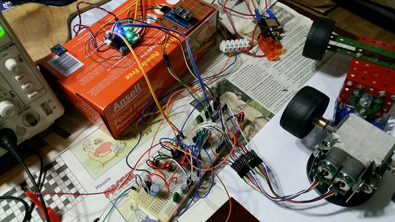
Background.
I am trying to build a rover with skid steering and quadrature encoders.
    2 PWM / 6 GPIO pins allocated as follows:

        PWM1    - Left Motor PWM      [MOT_PWM_TYPE = 3 (BrushedWithRelay)]
        PWM2    - Right Motor PWM      [MOT_PWM_TYPE = 3 (BrushedWithRelay)]
        AUX3    - Left Motor Direction
        AUX4    - Right Motor Direction
        AUX5    - Left Motor Encoder A
        AUX6    - Left Motor Encoder B
        AUX7    - Right Motor Encoder A
        AUX8    - Right Motor Encoder B
Thus I need all eight pins.
Michael