I use it for the magnetometer.
Ari.
I use it for the magnetometer.
Ari.
so you could trade pulse-type RCIn and buzzer for two additional PWMs / GPIOs using TIM3_CH1 and TIM4_CH1. as for now this is not gonna work using BRD_ALT_CONFIG though.
I use an FrSKY receiver. Are you recommending I switch the RX from s.bus to PPM
Ari.
i think i‘m getting confused here. initially i was brainstorming options to add PWM outputs in reply to what @brad112358 suggested. this would require to free TIM4. it‘s now used for RCIn, which can read both pulse-type (PPM) and SBus. RCIn via serial can only read SBus (and other serial protocols obviously), not PPM though.
so if you are using serial type RC only, trading RCIn on the LED pad as well as using the CAM_C pad for additional PWMs is an option. if you need PPM type RC, it‘s not 
OK, let me state what I’m trying to do. I think others have additional ideas that are valuable but orthogonal to my situation.
I have this board, an FrSKY RX, an mRo GPS+mag and a SiK radio.
I got the mag working through the pads labeled RX3/TX3 (I2C). I have the GPS working through pads labeled RX6/TX6 (SERIAL3 in AP).
I need to figure out where to connect the SiK Radio, without taking away my RC RX input.
Ari.
Yes, sorry if I confused things. There are two different threads of thought/conversation here.
@iter, As I said, and from what I can tell, your needs are met by the connecting things as described in the current arducopter docs for the V6 board. Did you look at the page I linked? You put compass I2C on RX/TX3 pads, GPS on RX/TX6, Telem radio on RX/TX1, Receiver SBUS on LED (labeled WS8212 on V6.1).
I’ve not tested an RC receiver on V6.1, but it works on V6 and it’s the same pin, so it will work.
Thank you @brad112358. I will try this and report back.
What threw me off was sbus inversion. I was under the impression that sbus needed an inverter. The pad labeled SBUS(RX1) appears to have an inverter between it and the microcontroller. The LED pad connects directly to the uC. I think you’re saying it’s OK to connect telemetry through an inverted RX line and regular TTL TX line; and that it’s OK to connect an sbus receiver to a regular TTL line without inversion.
Ari.
Extensively. This is how I was able to make any progress at all.
Ari.
OK. Now that you say it that way, I’m confused too. I need to look at the documentation for the radio I used and see what protocol RX protocol I used. Perhaps it wasn’t sbus. But the docs say it should work as it is one of “all RX serial protocols”.
Nope. I’m full of crap. It seems the receiver I used was probably outputting CPPM. The docs may be misleading unless there is some (un)inverting going on in the MPU, but I don’t think the F4 does that. I think that the LED pin works for every RX signal except what you want to use. Sorry. Can you configure your receiver to use something other than SBUS?
Also, the V6 seems to have both TX1 and SBUS pads. I assume just the SBUS pad is the inverted input. But I don’t see two separate pads on V6.1. This may be a problem…
“Change Logs” in the picture at the top of this thread it do say “6. SBUS receiver moved to RX1.”
If it helps, here’s a connection diagram I have from the vendor. It doesn’t show what’s inverted and what isn’t, nor what breaks out to pads. It does shed some light on their intent with the design.
Ari.
Yes, that diagram helps. Thanks!
I’m not sure how they think they can claim 100% firmware compatible. They must be talking about a particular firmware. I’m feeling cheated as it looks like many of us can’t use this board without some firmware work (or lifting a pin and adding a wire).
It looks like they took away the non-inverted RX1 pad; At least, I can’t find one on the V6.1 board. But, they did give us access to another pair of useful pins. I’m not very familiar with the way pin functions are assigned, but the data sheet makes me think that PB8 (PWM pad) and PB9 (PB9 pad) can be used for I2C or CAN bus. I think this could let us define a new board hwdef which uses RX/TX3 for serial instead of I2C.
I’ll try to dig into this, but if someone more familiar with writing hwdef.dat files wants to fix us up, please do!
This is all new to me. This is my third AP board (I have a PX4 Mini and Matek 405 Wing running smoothly) and I have some experience writing STM32 firmware, but I’m just learning about hardware management in AP.
Ari.
morning guys. sorry if i‘ve added confusion too.
as stated above, ardupilot will read both SBus and PPM on PB6, so afaik there‘s no functional change here, given that the WS2812 pad is really feeding PB6 on V6.x version.
as far as i can tell, the inverters have been moved from USART1 to USART6, plus there‘s solder-jumpers for inversion-control now. this won‘t be no functional change regarding USART1 (SERIAL1).
the most striking issue i see is that USART6 doesn‘t seem to be pinned out completely, i can see only one single UART6 pad on the new version‘s pinout scheme. please correct me if i‘m wrong! in this case, we’d only have one full serial port left.
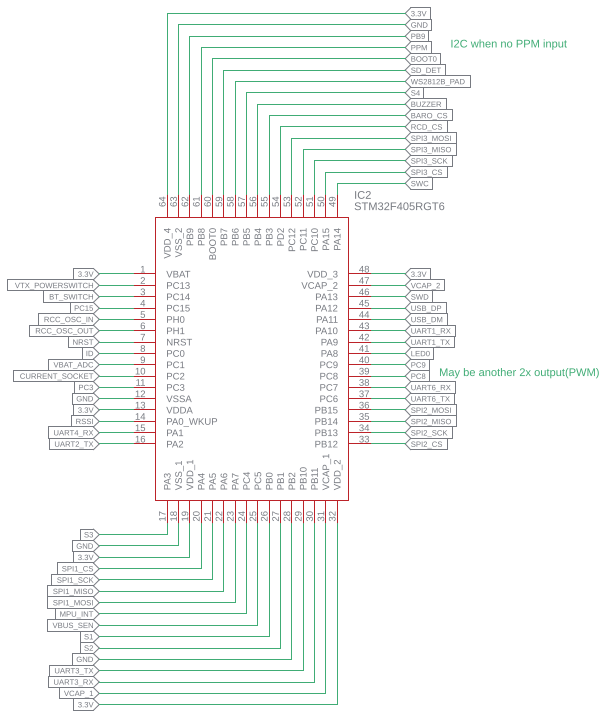
USART6 (SERIAL3): There are TX and RX pads on the back of the board that connect straight to pins 37(PC6) and 38(PC7). I have the GPS connected there and it works. On the front, there’s a pad marked F.Port(UART6) that floats by default. If you short the jumpers on the back, this pad carries inverted, combined (half-duplex) TX and RX lines like a yaapu cable.
USART1 (SERIAL1): Pad marked DSM2(TX1) connects directly to pin 42 (PA9). Pad marked SBUS(RX1) connects to pin 43 (PA10), but through an inverter. With existing firmware, USART1 is usable for SBUS input, but not for bidirectional operation since the RX line is inverted but the TX is not.
The pad marked WS2812 connects directly to pin 58 (PB6). You could replace
PA10 USART1_RX USART1
with
PB6 USART1_RX USART1
in OmnibusNanoV6/hwdef.dat and get a full-duplex, uninverted USART1. In this case, it is my understanding that you would lose the ability to read SBUS on SERIAL1, since it requires inversion.
Ari.
That solves half of Ari’s problem.
But, PB6 doesn’t have UART function, does it? Is RCIN doing software serial?
But, another big problem remains. They seem to have eliminated the non-inverted input for RX1 (PA10). V6 had both inverted and non-inverted inputs, labeled SBUS and RX1. I think this eliminates one serial port for us. But, with your change to make RX/TX3 available for serial, I think we can just add support for I2C on PB8 and PB9.
I’ve only ever made minor tweaks to hwdef.dat files, but this should be straight forward, shouldn’t it? And, I’d think we could just keep the one hwdef for both V6 and V6.1 with V6 each just not implementing some of the connections. Would you have advice or want to help with this?
Thanks!
sure, i’ve ordered a V6.x for testing as i‘m not that familiar with inverter handling honestly. good to hear there‘s both a TX6 and RX6 pad on that board!
btw: has anyone of you actually tested SBus on ws2812 pad? we don‘t have softserial in ardupilot, but timer-based RCInput softsigreader afaik does the job. correct me if i‘m wrong please.
What are the relevant parameters to set to tel AP to expect SBUS there?
Ari.
no special settings required, it should autodetect.
@ iter, For V6.1, it won’t really matter if SBus works on the ws2812/LED pad, since we can’t use RX1 for serial anyway, you can connect it there if it doesn’t work on the LED pad. I suggest try it. It’s just one wire to move.
@vierfuffzig, You mention you have ordered V6.x. Will it be V6 or V6.1?