@MHefny i was wondering why you decided to NOT use the Hardware PWM units on the raspberry for PWM creation, but instead create the PWM with a external chip?
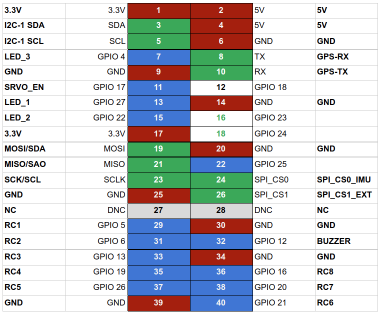
There are 4 available on two row pinheader, which would fit quite well for a Quadcopter usecase: PWM at Raspberry Pi GPIO Pinout
There are more available if one plans to build a custom CM4 board.
UPDATE: its actually only 2 PWMs signals but on 4 pins.
Hi,
This scenario may fits but only for quadcopter, and may affect the ability to run ardupilot app itself because of handling this pwm.
my latest solution which is much better is https://medium.com/@mohammad.hefny/ardupilot-linux-based-system-stm32-as-a-breakout-module-part-2-5db4ce7cfe3e which uses a complete co-microprocessor to generate PWM and other ESC signals. It also enables using other boards rather than RPI, maybe Mango -I hope-.
My solution is not final yet. It happened to be betaflight, but nothing is final yet.
Also I am not using the flight control system. I am selecting some libraries and building some.
Glad that you liked it.
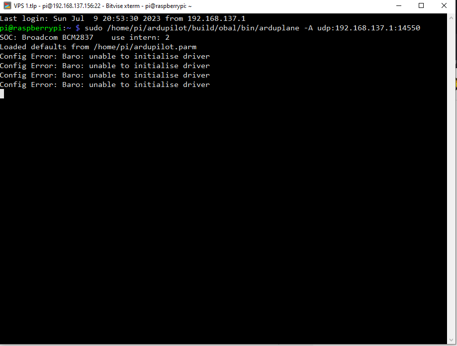
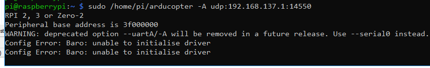
Hello, I am a beginner and I’m having some difficulties. I am using a Raspberry Pi 4 (Linux raspberrypi 6.6.69-v8+ 1 SMP PREEMPT Sat Jan 4 21:36:40 -03 2025 aarch64 GNU/Linux) and I have modified the kernel (like this: Running Ardupilot on Raspberry OS-64 (bullseye) | by Mohammad Hefny | Medium). I built the code following the instructions from this guide:
git clone GitHub - ArduPilot/ardupilot: ArduPlane, ArduCopter, ArduRover, ArduSub source
cd ardupilot
git submodule update --init --recursive
make obal
./waf configure --toolchain=/opt/cross-pi-gcc/bin/arm-linux-gnueabihf --board obal
./waf sub
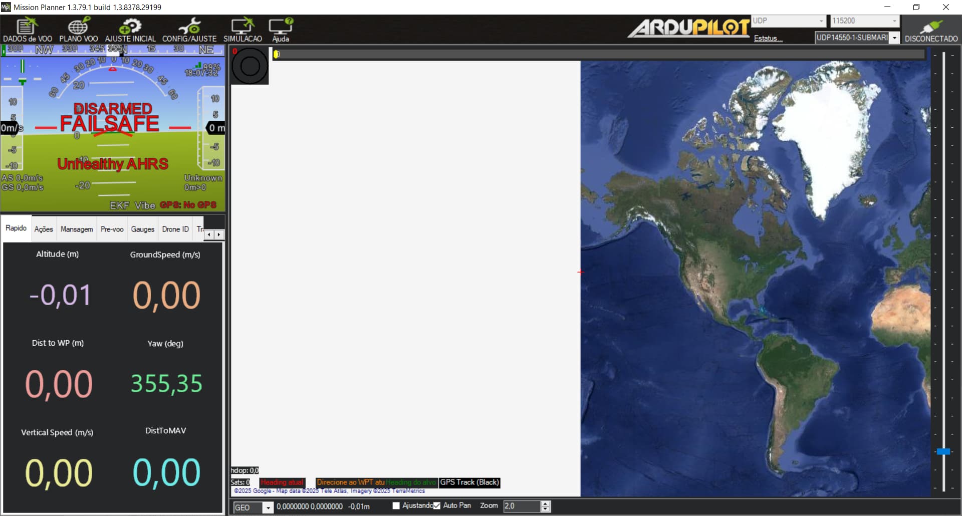
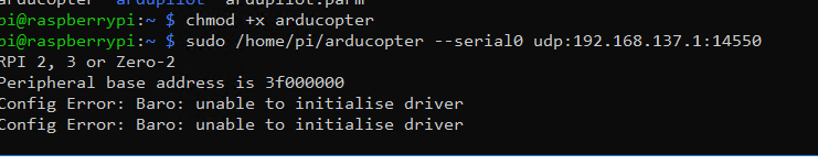
nano /home/pi/ardupilot.parm
SYSID_THISMAV 1
FRAME_CLASS 2
FRAME_TYPE 0
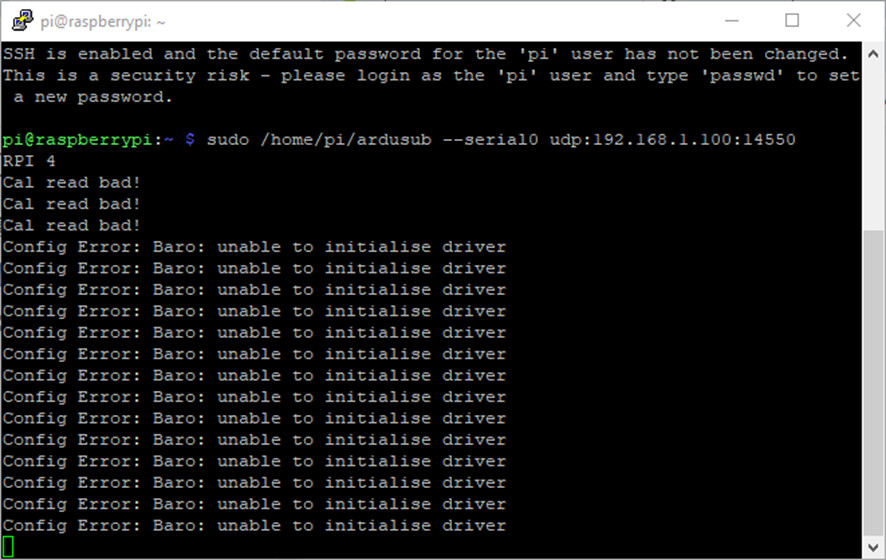
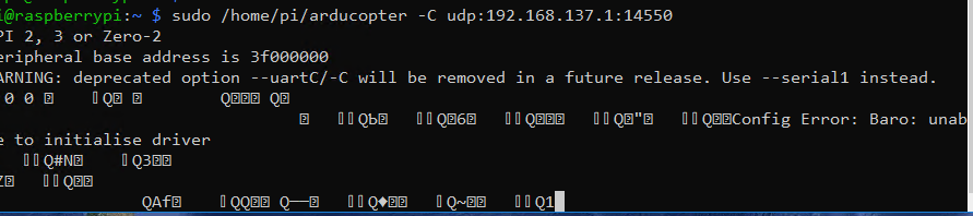
sudo /home/pi/ardusub --serial0 udp:192.168.1.15:14550
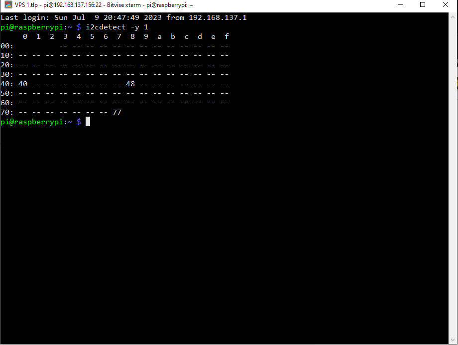
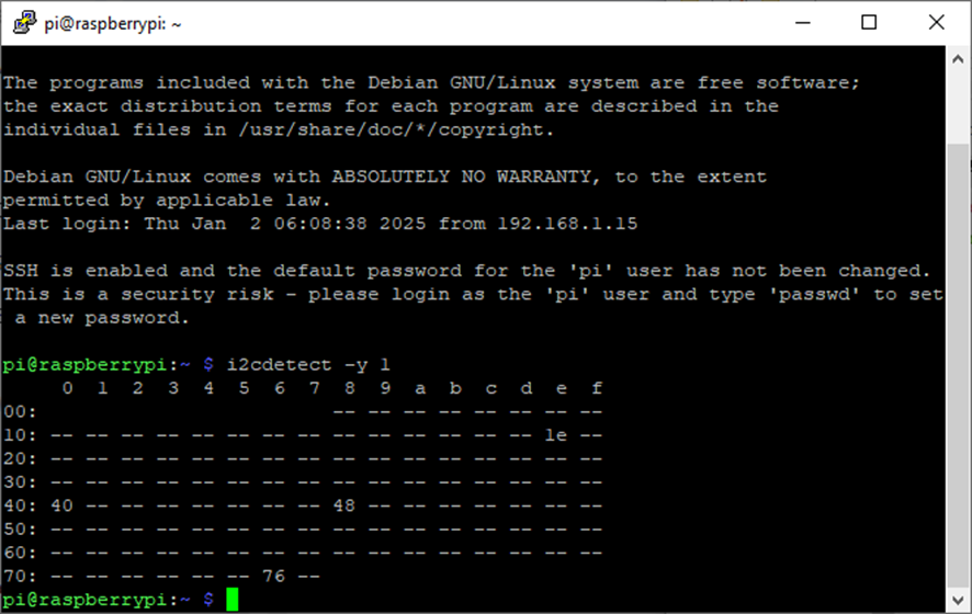
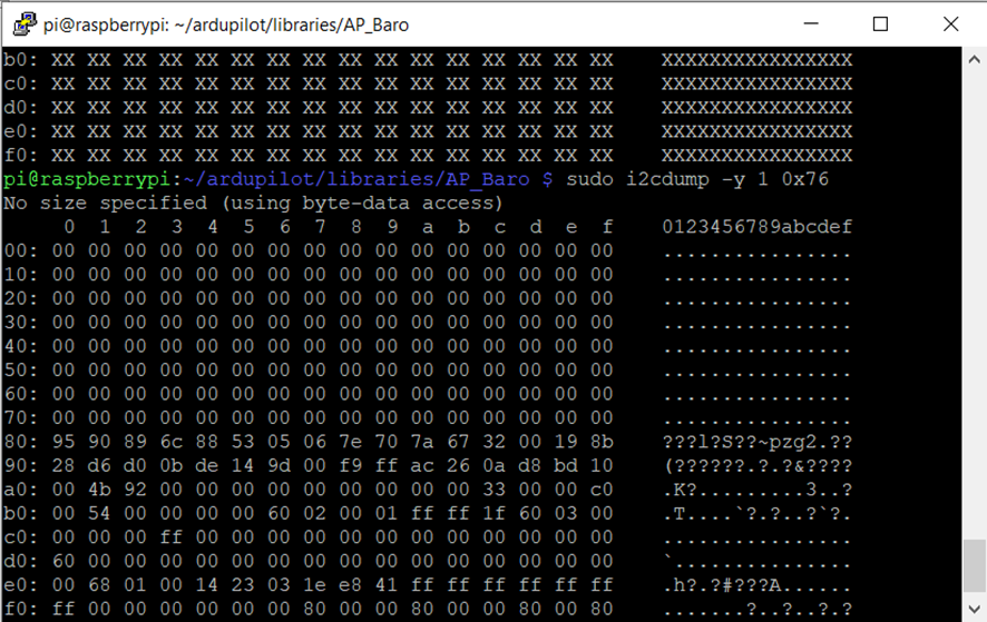
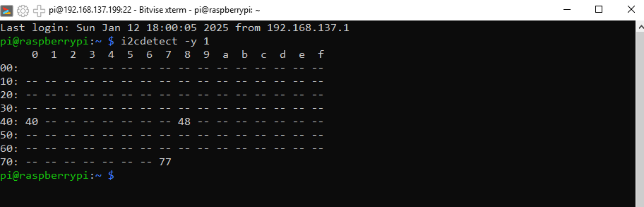
First of all, thank you for your prompt response. Initially, I was using a sensor I had purchased as a BMP280. After asking, I continued testing and discovered that it was detected at the address 0x76 0xD0 0x60, which means it’s actually a BME280, and perhaps that’s why it didn’t work.
After that, I tried a sensor I use with the Pixhawk, the MS5837, but it also didn’t work initially. However, when I tried again to respond to your question, it finally started working. Most likely, the first time I tried, I connected the sensor to the same bus as the BME280 with the same address, which must have caused a conflict. Now, after disconnecting the first sensor, it’s working perfectly!
I feel a bit embarrassed because I had tried extensively before asking, but at the same time, I’m very happy that it’s now working.
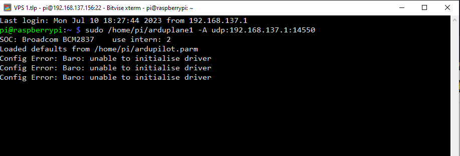
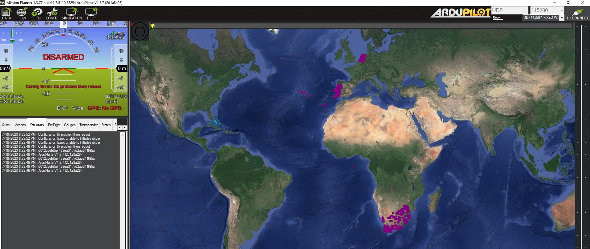
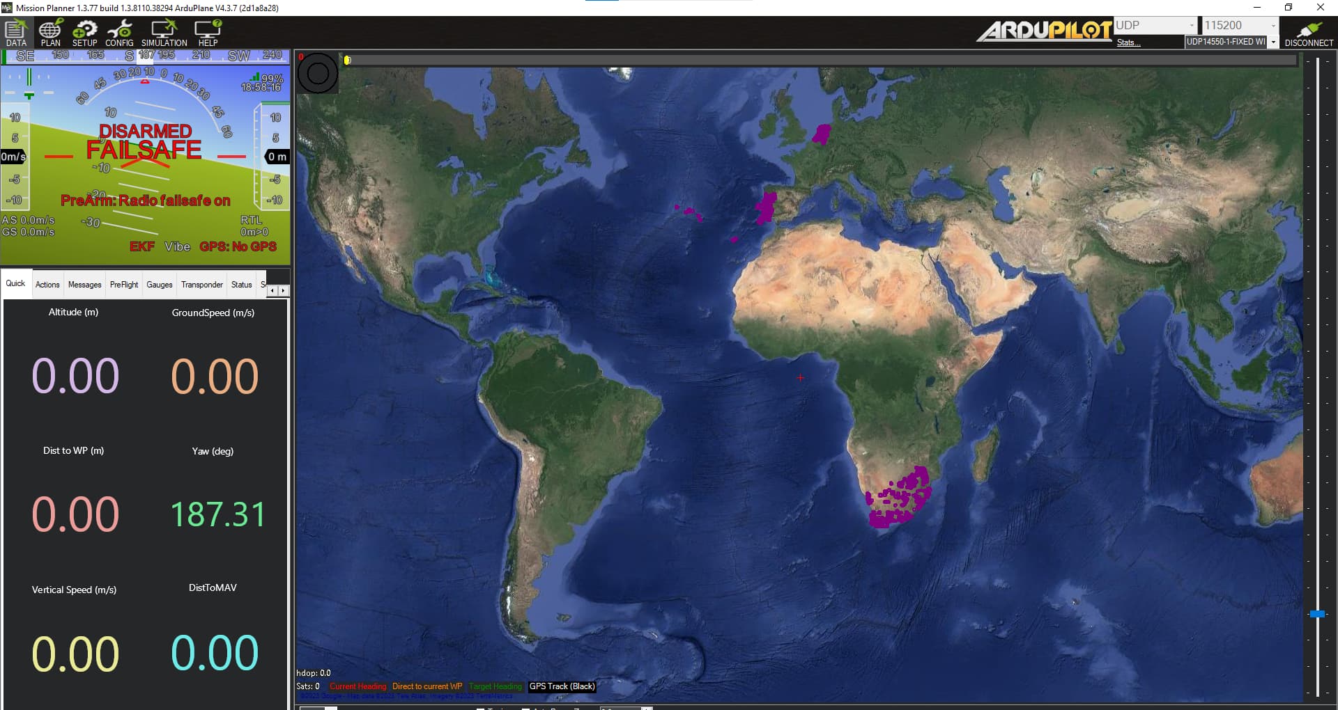
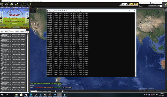
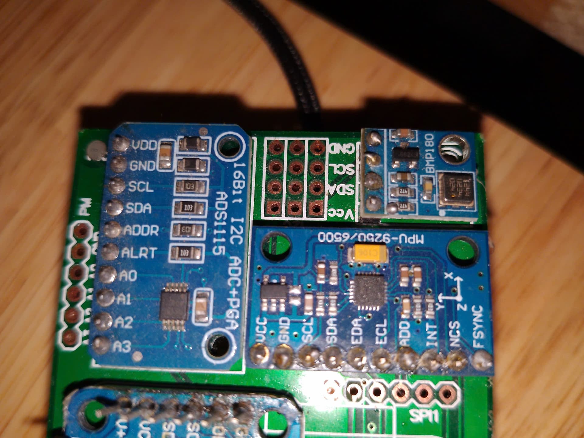
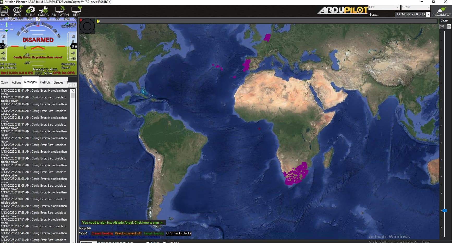
hi, did you find the reason why Mission Planner can’t connect OBAL board? I am also having the same problem. The baro sensor I use is BMP180. I tried all the parameters but still can’t make it work can you share your experience with me
I used to run Ardupilot well and successfully connect to Mission Planner on this board built a few months ago. But then I temporarily put aside the work of testing this board.
Now I go back, do exactly what I did and I have this problem again.