Notch filter center frequency

I have a few questions about how I should go about setting up the harmonic notch filters in ardupilot. I have read through all the documentation on it but I just wanted to be certain before I move forward since crashing this particular drone is not an option for me.

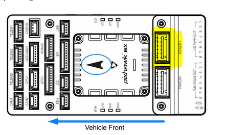
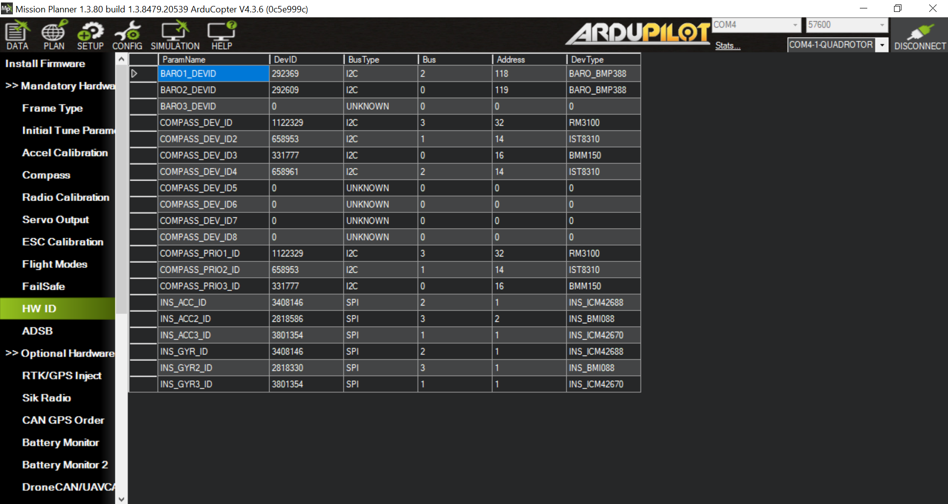
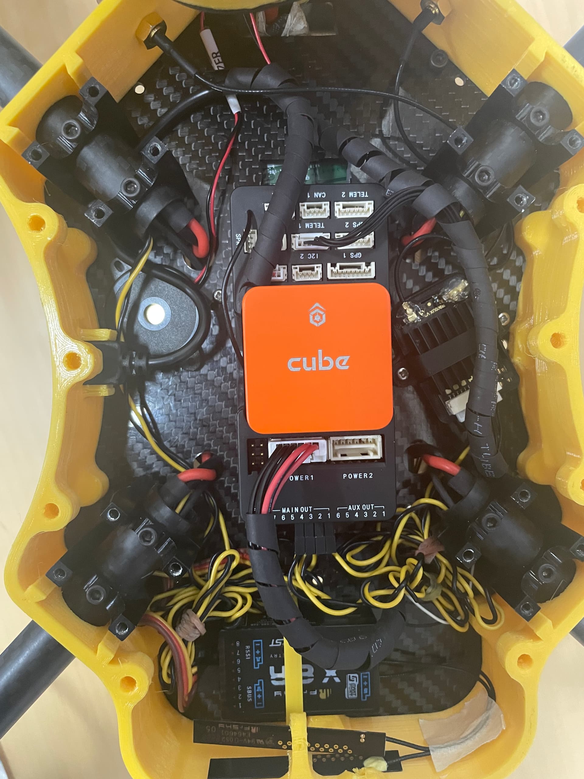
I am currently in the process of tuning a large quad rotor that will eventually be a gas hybrid platform. It has about 43in props and the flight controller is a pixhawk 6x. Due to the high vibrations I anticipate, the Pixhawk is mounted in a similar fashion as in this tutorial. The vibrations do seem low so I believe that is working but the engine is not currently running.

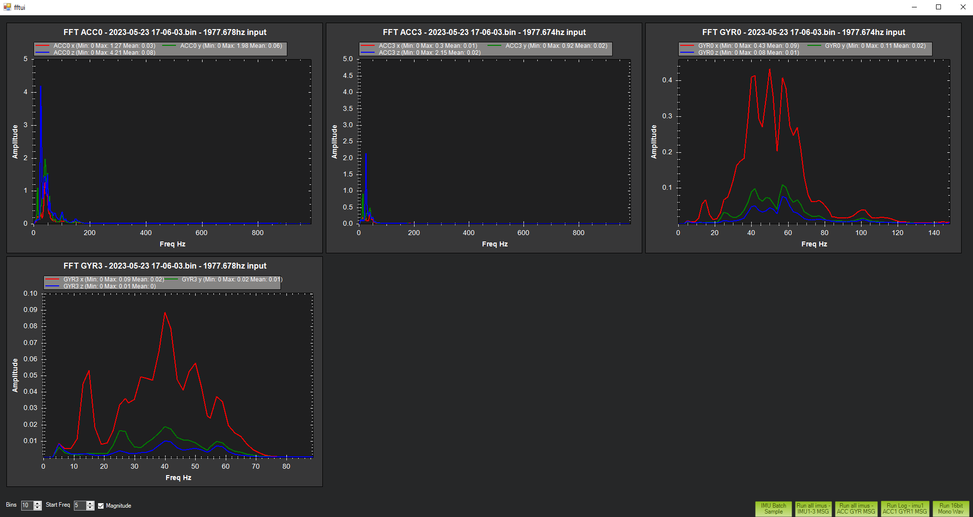
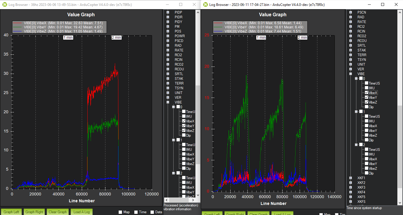
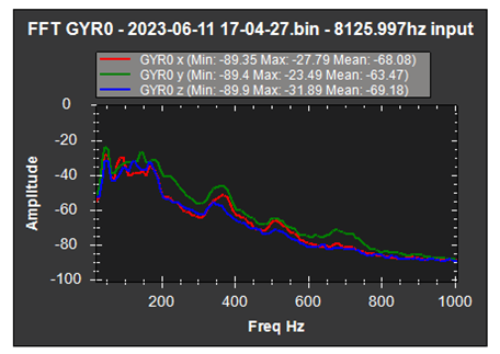
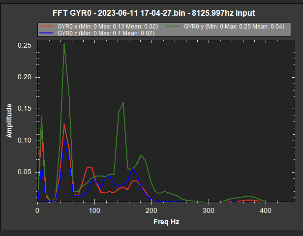
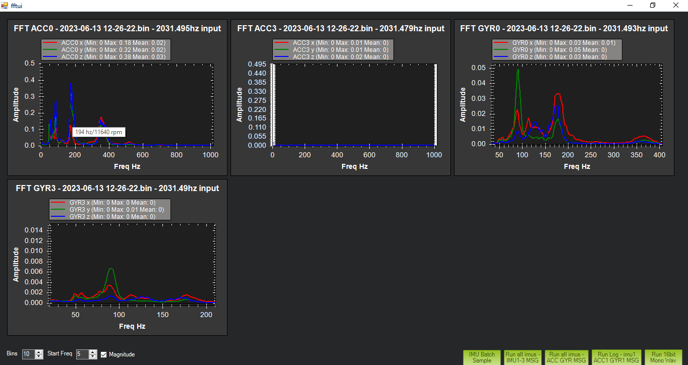
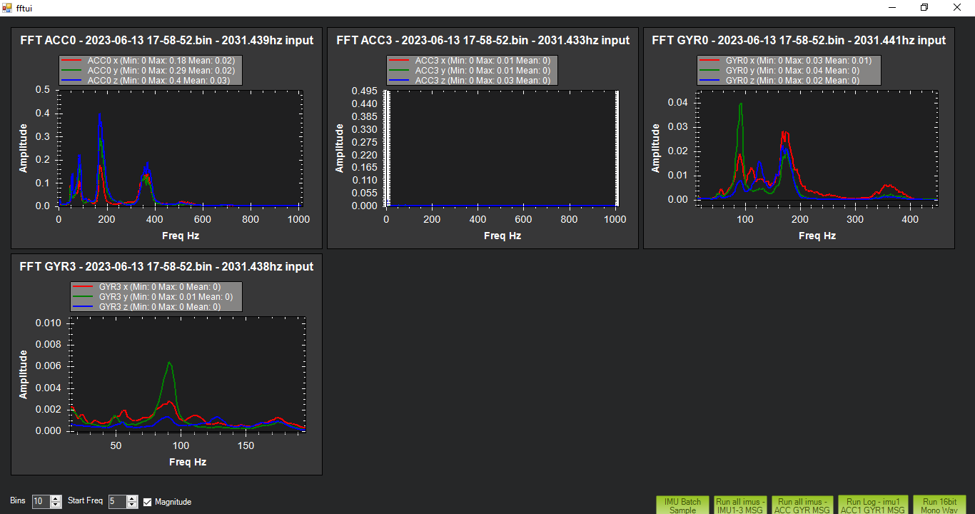
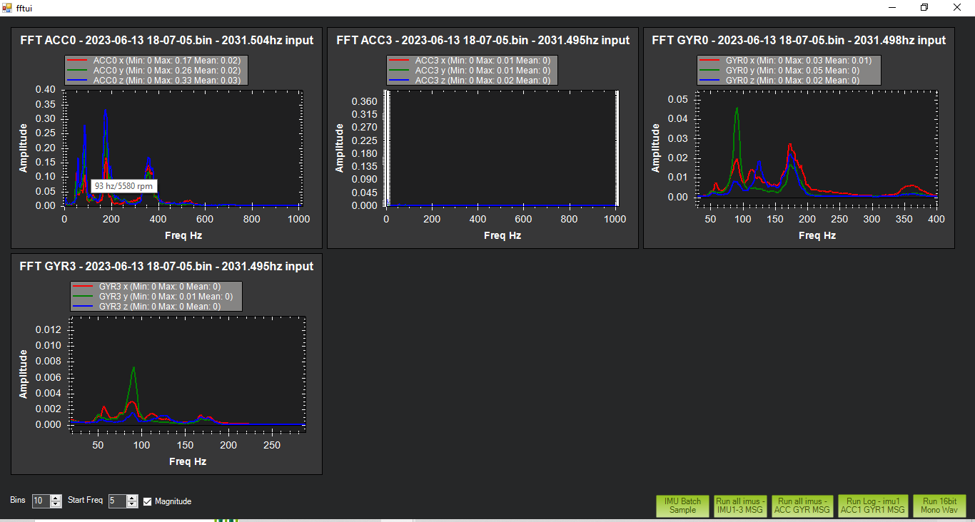
In regards to the notch filter I would like to set that up before I continue tuning but after downloading the logs the graphs look like this:

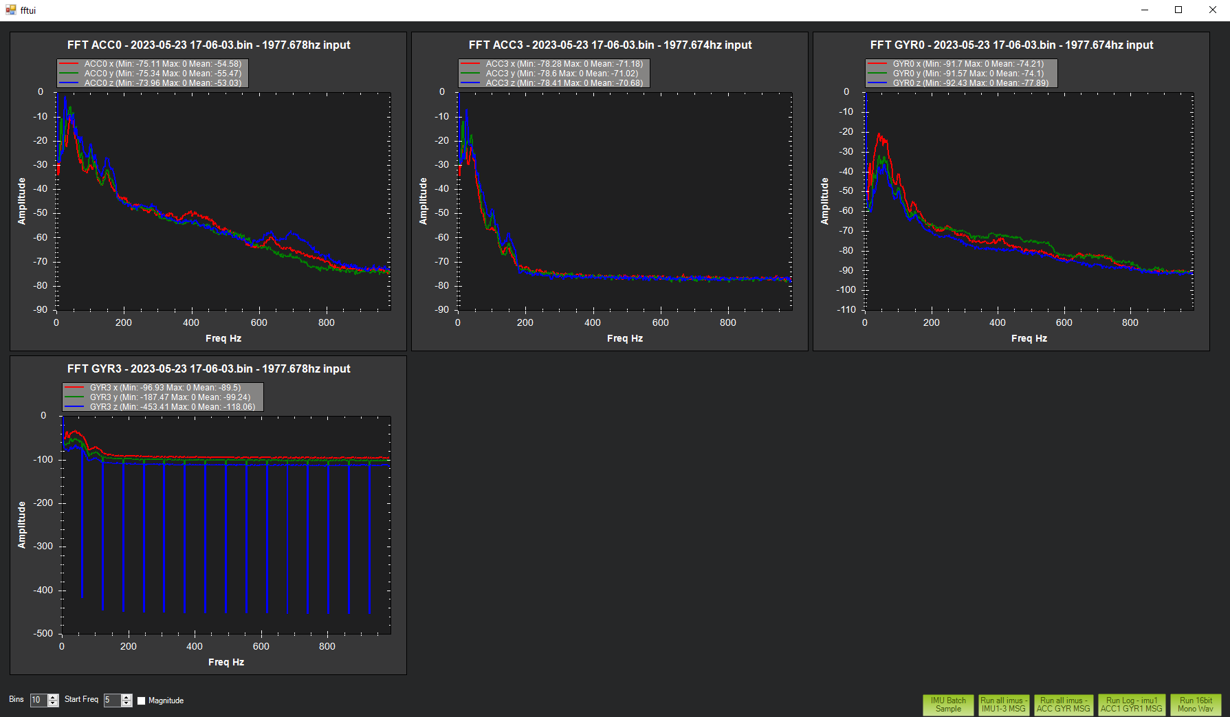
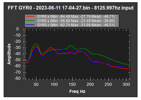
There are very strange lines coming down off the GYR0 plot and I am not sure if this is a cause for concern so I was hoping I could get some clarity on that. My main question is what should the centering frequency be set to when the GYR0 and GYR3 plots center at slightly different peaks (40hz and 55hz)? Also on the GYR3 graph there is a small peak at 100hz after the main peak, would it be worth it to set up a second notch for that? Iā€™ve read that setting up a double notch can be counter productive. There is also a noticeable separation between the three lines and I am not sure if that is normal as well.

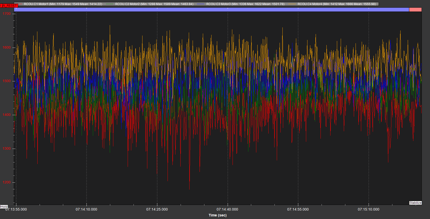
The tune is still quite poor but that is a work in progress, if you had any suggestions on how I should adjust the tune Iā€™m all ears. I have been against using autotune since Iā€™ve had a bad experience with it a few years back.

Thanks for all your help I really appreciate it!

Log file can be found here

1 Like

When checking FFT for setting up the harmonic notch filter, it is best to set the Magnitude option
image

I cant check your log because it seems the FFT graphs dont work for the .log format, at least not for me.

But anywayā€¦
For 43inch props you will need to start with these

ATC_INPUT_TC,0.22
INS_ACCEL_FILTER,10
INS_HNTCH_REF,0.18
INS_HNTCH_FREQ,30
INS_HNTCH_BW,15
INS_HNTCH_FM_RAT,0.7
LOG_BITMASK,180222

and I advise setting
FENCE_ENABLE,1
and check the other fence parameters - altitude and radius.
And experiment with GPS_GNSS_MODE and GPS_GNSS_MODE2 and what works best for your area.
Only select 2 constellations, usually GPS + GLONASS or Galileo. Only select SBAS and other option if you know they are actually available in your area.

You will definitely need to set up voltage monitoring at least - all the values are present in your parameters but there is no voltage to record. try to get this working before any more flights.

With those big props you will want to run the VTOL Quick tune script before you go any further. Make sure all your MOT_THST_EXPO , MOT_PWM and MOT_SPIN params are correct and suited to your ESCs first.

2 Likes

My apologies, here is the bin file for your reference.

I will give those params a shot and see if there is a noticeable difference.

After setting the magnitude option it makes it a bit more clear that I believe it should be centered around about 40hz:

Iā€™ll need to flash to the 4.4.0 beta to allow for the voltage module to work but I was a bit hesitant since itā€™s a beta. Do you recommend I attempt the quick tune before I go ahead with setting up the notch filter? The loiter is still a bit unstable so I really do not want to put this thing at risk of crashing during the tuning stage.

The problem is the motor outputs are very spread, giving you that very wide spread of frequencies in the FFT graph.

So you should first check COG and check that your motors are all perfectly level and the frame is not twisting under load. At the moment you may have weight shifted towards Motor4, but I think itā€™s more likely a twisted motor mount or frame. The easy check is to see if all the prop tips ā€œpoint to each otherā€ in perfect alignment.
image

When the motors are all running with a more even load, the FFT graph will show us a much more defined frequency range.

Why a firmware change for voltage monitoring? Are you not using the I2C based monitor that came with the 6X ?
I would definitely stick with the stable firmware release - with any large props you do not want any unexpected behaviours.

At this stage use all the parameters I already suggested, except change

INS_HNTCH_FREQ,40
INS_HNTCH_BW,40

This bandwidth is really too wide and may give issues, so try to stick with INS_HNTCH_BW,20 until more is known and other issues are sorted.
Plan to do that VTOL quick tune with the next flight too.

Especially with these big copters the build, tuning and general flight is a ā€œwhole packageā€ so just changing a couple of params and attempting flight again rarely fixes much - you need to work on everything (like motor mount twist) in conjunction with the updated parameters to get better flight.
I just mention it because so many people try just changing one thing they had focused on and go test again - this is not so bad with a small quad where the danger is low.

1 Like

Wow you really know your stuff I appreciate your support on this! You were right, I leveled all the motors prior to tuning but it looks like 3 of the motors were knocked out of level about 1.5 degrees all in the same direction. That explains why motors 3 and 4 were working a bit harder to counteract the yawing moment. The engine is mounted rearward and the gas tank is empty so there is a bit of a bias toward the rear motors right now but I felt like tuning it again at full weight would be better than going straight to that configuration.

The 6x only accepts digital power modules and the one included was only a 6s, I purchased this 12s power module but it is only supported in the beta so I have no choice but to use it for tuning at least. Iā€™m not sure what I am going to do about this since I have no other option, Iā€™m not well versed enough in ardupilot to make a custom firmware that allows for the voltage module to work through I2c.

I went ahead and set those params and attempted to run the quick tune without a voltage module. I was unable to begin the quick tune since the initial oscillations in loiter were already far too great, I was messing with the PIDS in an attempt to calm it down but it was consistently too violent to begin the tune. Itā€™s performance in stabilize is flyable but in loiter it oscillates in both pitch and roll. Struggling to find any guidelines in terms of the proper way to set the stabilize error rates and acceleration values but I donā€™t think that is the root cause of my problem.

In other news the corrections to the motor level seemed to help bring all the thrust values closer together which is great. Looking at the new GYR3 plot it seems to have improved as well but it was not in the air for very long.

Please let me know what you think of the log as I have not been able to solve this loiter issue for a while.
Thanks again for all your help!

Stick with using Stabilise and AltHold until that quicktune and more tuning has been done, then we can work on Loiter.
Loiter itself is usually not the problem, but because it is trying to hold a specific position the position controller places more demands on attitude control which will ā€œenhanceā€ any issues you have hiding.

Thatā€™s weird - Iā€™ll look into that more.
I would have thought that the only difference would be the voltage and current data, not the connectivity.

What ESCs do you have?
I suspect these are a bit wrong

MOT_PWM_MAX
MOT_PWM_MIN
MOT_SPIN_ARM
MOT_SPIN_MIN
MOT_THST_EXPO

Set these PIDs ready for the next flight to try and improve the oscillations before running the quicktune

ATC_ACCEL_Y_MAX,8000
ATC_ANG_RLL_P,4.0
ATC_ANG_PIT_P,4.0
ATC_RAT_PIT_D,0.0034
ATC_RAT_PIT_I,0.12
ATC_RAT_PIT_P,0.12
ATC_RAT_RLL_D,0.0034
ATC_RAT_RLL_I,0.12
ATC_RAT_RLL_P,0.12

But please dont fly until youā€™ve confirmed those ESCs for me because this information might change a few things and some behaviour.

Can quick tune still work in alt hold? I though it waits for 4 seconds after pilot input to begin tuning?

There is little to no documentation on the ESCs I have but I settled on them due to the efficiency ratings for the full power system, I can reach out to the manufacturer if you are looking for any specific information however. I believe those params are set mostly correctly as far as I know, I tried setting mot_pwm_min to 1100 but two of the escs would not arm so I had to revert back. Additionally the minimum speed to get all the props rotating is quite high but it is set correctly (esc calibrations would not fix this I tried multiple times). Mot_thst_Expo on the other hand Iā€™m not sure, I used the calculator and it said to set it to about 0.85 but from what Iā€™ve read with quicktune setting it lower will help based on the ESC you have. I could not find any information on whether or not these escs use linearization so I have it set a bit lower just to be safe.

I will try those PIDs tomorrow when the wind dies down, hopefully they will allow me to loiter so I can run the quick tune.

Thanks again,

They look suspiciously like the T-Motor or Hobbywing integrated power units, or copies.
Itā€™s disappointing and somewhat crazy that they cant supply the most basic info, and the support page just has nothingā€¦ not even links to information.

I would set
MOT_PWM_MIN,1100
MOT_PWM_MAX,1940
and use motor test to recheck those MOT_SPIN_ARM and MOT_SPIN_MIN values.

Your MOT_THST_EXPO will be Ok until we see more results.

At the moment I cant find any special updates for the PM02D but Iā€™ll keep searchingā€¦

Do you have it plugged into Power1 ?
image

Try changing the BATT_I2C_BUS

Also can you show a screenshot of the MissionPlanner / Setup / HWID screen please

EDIT
Found it!
This Pull Request went in just 2 weeks ago, to support a slightly different I2C power monitor chip
The new chip might appear on BATT_I2C_ADDR,45 instead of 65 - you can set 0 to probe all valid addresses. I dont think this will work for you though, until the stable firmware is updated.

1 Like

Yes they do look fairly similar and I wish I could have bought the kit from T motor instead but the efficiency and thrust rating of this power system was hard to beat. The lack of documentation is very disappointing but I canā€™t argue with the price to performance.

I tried setting MOT_PWM_MIN to 1100 but again two of the escs would not initialize after pressing the hardware safety switch. MOT_PWM_MAX was set to 1940. I used motor test to set the mot spin arm and min values and those are indeed the minimums, I made them a bit lower but any lower and some of the motors donā€™t rotate while others do.

Here is a screenshot of the HWID screen:

Wow thatā€™s a nice find! Yes I had the power module plugged into power1, but messing with the BATT_I2C_ADDR could not get the power module to report any data. They say the defaults are supposed to just work and it did with the 6s module but running it on a voltage stepdown wouldnā€™t do much good for me.

The tune worked a bit better, I noticed that there were still oscillations in loiter but they were less than before. Unfortunately attempting the quick tune resulted in the drone crashing pretty violently so I think I will be stepping away from ardupilot at least for the near future. I felt like I was really close to getting it working right but since I couldnā€™t nail the root cause of this issue it would be too expensive to try again to continue testing. But thanks again for all your help I did really appreciate it.

Facing Issue to determine center frequency and band width of harmonic notch filter. After Initial Flight tuning (PID and Gyro Filter) we are going to setup the Notch Filter of our newly customized Copter, specifications are followed:

Autopilot: Pixwhak Cube Orange (ADS-B)

Motor to Motor Dis: 600mm

Propeller: 13ā€

Motor: TMotor MN3510-13, 700kv

Battery: Li-ion 4S

TakeOff Weight: 3.2 Kg

Parameters:

P&I = 0.101, D=0.0036

Gyro Filter = 36Hz

Foam Damper = 1.5mm

Before Damper and after damper graph:

FFT Dataā€“ IMU Batch Sampling (Sensor Rate Logging):

The Graph of 1st Set of Harmonic is followed:
Without Zoom
image

Zoomed
image

There all the axis are having different vibration peak & very large FTN1.BwAvg (135), we tried Harmonic-Notch with this base frequency (49Hz, bandwidth-135), but drone started oscillating violently after activating FFT based Harmonic-Notch.

We also tried the harmonic notch band-width with 135(Log), 25(Log) and 49(Log) but the noise was not notched effectively.

:pray: Can anyone mentor us that, how we can eliminate those noises with efficient manner!

Here is log before setup Harmonic Notch: Log

Here is log after setup Harmonic Notch: Log

Set this and re-run the hover flight.
INS_LOG_BAT_OPT,4
Before loading the file in the FFT Viewer check the ā€œMagnitudeā€ checkbox. The log scale you are showing is not useful for this purpose.

1 Like

This is what your graph looks like, you have to select ā€œMagnitiudeā€ in the bottom left.
image

Because your motor outputs are oscillating there are a whole lot of frequencies and noise in that graph.
Typically the main frequency for 13" props would be around 70Hz - so the 87Hz peak could conceivably be the motor noise. Thereā€™s something else going on at 47Hz, like a harmonic or something loose.

1 Like

Thank you @xfacta, updating soon after another test-flight.

We did another flight,without enabling harmonic Notch log

We did another flight with throttle based harmonic notch, with the following frequency and bandwidth
HNTCH Center frequency= 62Hz, Bandwidth=31


^Log

HNTCH Center frequency= 90Hz, Bandwidth=45


^Log

It was surprising to see that noise was already reduced without notch.
Post notch we couldnā€™t see any improvement or change with noise reduction.

With this setup, Is it good enough for us to proceed with PIDā€™s tuning?

Thank you

Not surprising. The Low Pass filter does this.

I couldnt understand why you would the harmonic notch filter at 62Hz, that is not a significant frequency peak in your data - 90Hz was close though, and even the in-flight FFT was targeting 60Hz which is a bit odd.

This would mean the filter is working down to 49HZ - (135/2) = 49 - 67.5 = -18.5 Hz which is impossible, and it filters out all the actual movements and control frequencies that are needed for operation.

Anyway, I would set these for a dynamic notch as per usual, and a static notch targeting the odd low frequency and itā€™s harmonic. And uncheck the fast FFT logging too

FFT_ENABLE,0
INS_HNTCH_ENABLE,1
INS_HNTCH_MODE,1
INS_HNTCH_REF,0.22
INS_HNTCH_FREQ,88
INS_HNTCH_BW,40
INS_HNTCH_HMNCS,7
INS_HNTCH_FM_RAT,0.7
INS_HNTC2_ENABLE,1
INS_HNTC2_MODE,0
INS_HNTC2_REF,0
INS_HNTC2_FREQ,55
INS_HNTC2_BW,20
INS_HNTC2_ATT,40
INS_HNTC2_HMNCS,1
LOG_BITMASK,178174

For PIDs try this, take off in Stabilise mode, of oscillations are worse put them back to how they were. If all is Ok then use AltHold mode. Dont use Loiter until tuning is a bit better.

ATC_ANG_PIT_P,6.0
ATC_ANG_RLL_P,6.0
ATC_RAT_PIT_D,0.0033
ATC_RAT_PIT_I,0.100
ATC_RAT_PIT_P,0.100
ATC_RAT_RLL_D,0.0033
ATC_RAT_RLL_I,0.100
ATC_RAT_RLL_P,0.100

Today, Flight was more stable with your recommended PIDs and Notch Setup
First Flight with Stabilize and AltHold (Log)
Second Flight with Loiter Mode (Log)

We are grateful for your valuable inputs for the setup. :heart_eyes: @xfacta

In previous flights
Gyro Noise without Harmonic Notch (Log)

Gyro Noise after acitvating Harmonic Notch (Log)

From above we can see that Gyro noise with and without Harmonic Notch is similar,
so, do we need to activate harmonic notch. Is Just the gyro filter enough to handle this Noise?

We are planning to initiate Auto-Tune with the PIdā€™s and notch input given from you @xfacta , if Auto-Tune is not providing satisfactory tune then we will proceed with manual tuning.

The normal gyro filter is just low pass, so it does tend to get rid of a lot of noise above the designated frequency - that is itā€™s job.
You are correct that there does not seem to be much difference between with or without the harmonic notch filter in this case, but there is a tiny difference. Iā€™m not sure why that is - can you supply a photo of the flight controller and surrounding area?
There is still that annoying 40 to 60Hz noise aside from the main prop and motor vibration at around 90Hz.
You could try using INS_HNTCH_OPTS to enable double-notch or triple-notch to see if that makes a difference, rather than trying to add in another static notch.

I think Autotune would work OK anyway, since generally vibrations and noise is low despite there being bit of a spread of noise. I think thatā€™s just because the copter is a bit under-powered. Attitude control is reasonable at this point.

Any reason to be flying on firmware 4.4 DEV ?

If you have a 4S Lipo DEFINITELY set these:
BATT_ARM_VOLT,14.70
BATT_CRT_VOLT,14.00
BATT_LOW_VOLT,14.40
MOT_BAT_VOLT_MAX,16.80
MOT_BAT_VOLT_MIN,13.20
BATT_FS_CRT_ACT,1
BATT_FS_LOW_ACT,2
If you have a different battery pack then use the Initial Parameters calculator to set the correct values for these. Always have those BATT_FS parameters in place.
Weā€™ve seen so may people thinking they dont need these, especially during ā€œtestingā€, and it doesnt end well.

Autopilot and surrounding area

We did with thriple notch and the results were same.
(Log)

Autotune Roll Axis
(Log)

Pitch axis was failing and recommending to perform manual tune.
(Log)

Frimware dev because we have made the firmware secure boot loader so that we can lock the parameters for end use.

We are using 4s Li-ion
BATT_ARM_VOLT,13
BATT_CRT_VOLT,11.20
BATT_LOW_VOLT,12.0
MOT_BAT_VOLT_MAX,16.80
MOT_BAT_VOLT_MIN, 11
BATT_FS_CRT_ACT,1
BATT_FS_LOW_ACT,2

Noted : we will ensure batt_FS parameters