Just FYI I put an ultra low esr 1000uf cap on each of my esc power leads right by the ESC input teminals. Keeps everything happy and cleans up the signal
Why did you pick 1000mf and not 330 or 470 like most ESC vendors use. Just curious.
Because I am extra like that  . But in all seriousness the 1000s fit perfectly in a 25mm tube.
hahahahaha
Ok that works for me.
@Patrik_Emilsson
Hey Patrick can you do me a favor and check this log for that magic Compass interference thingy you have been doing.
I have the new RM3100 and curious how its performing.
I had no GPS glitches today. One EKF variance only and that didn’t last long.
This is the most recent log
Hi Dave, I agree with you to install “big” capacitor, could you please advise us what brand or model that really “Ultra Low” esr capacitor?? And also how to make sure that those caps. are really ultra low esr type ?? Thank you…
Are you sure it was a 1000mF cap? Or was it a 1000µF cap? (Milli vs. micro)
I corrected the post. Yes… uF
A 1000 millifarad (AKA 1 farad) capacitor would be quite the payload and I don’t think they would fit in the arm tubes  I had a couple of those lying around from my younger days, I gave them to the neighbor kid so he can antagonize me further with his car sub woofer
@dkemxr wait… you mean you are not running 150mm arm tubes? lol
Yeah I did mean 1000uf caps.
I am using the Panasonic FM series which are low esr caps
Here is a pic of how I do the caps. There is about 1.5 inches if red/black wire after the cap that gets soldered to the ESCs
Very nice Dave,…will keep this method in mind.
Hi Ricky, I think it looks very good.
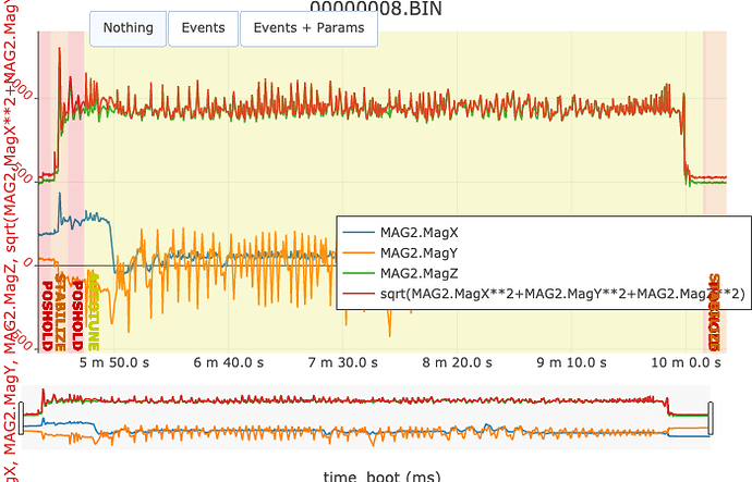
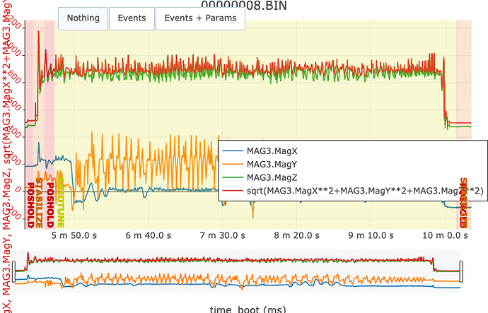
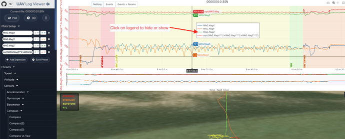
You seem to have three compasses in your system and Compass1 is definitely working good.
The red line should be as straight as possible and for Mag1 it’s pretty good. If anything it might be a little off in calibration of the x axis. You can see when MagX make big dip the red line increase.
I checked and you dont seem to have any interference from current.
I hope you now will have some good flights! 
Thank you Patrick @Patrik_Emilsson
I am not sure what you mean about the big dip on mag1 but will take your word for it. Mag 1 is the Drotek RM3100.
Funny I disabled compass 3 yet it’s reporting here, I also confirmed this morning that compass 3 is disabled so I assume it still is capturing data but it’s not being used.
I did an in field compass calibration this morning before flying. So hopefully the compass performance is even better. No EKF variance this morning and no GPS glitches.
I did get a battery failsafe…dang I need to tweak that a little.
Here is the log.
I hate to keep asking so I need your guidance on how to set up the log viewer. I tried but I keep getting some strange graph nothing like yours.
Also the log states I had a battery failsafe at
09:04:26 Battery 1 is low 20.17V used 2440 mAh
But no where can I find a battery reading that low in the log.
This is what I get and it’s nothing like your graph. I can’t figure out why.
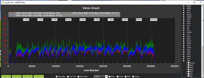
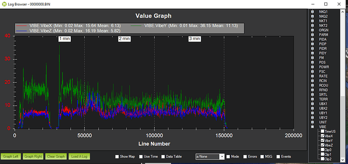
The other thing I just can’t seem to solve is the Y Axis vibes.
Even after rebuilding and upping the isolation the Y Axis still is high.
This is old graph
This is new…Much better on Z and X.
But not why.
No clue why
Hi, I’m sorry you ran out of battery I hope it survived.
I have no problem answering question and learning, isn’t why we are here 
I find stuff daily 
First the compass menu I found under “presets” on the left
You can then move the window containing legend names by left click and drag.
If you want to hide you click on the legend itself
There seem to be two battery values in the log, one was hitting 20.17
I don’t know why there is two battery levels, I have to search for that
I have had a number succesful flights during this weekend, no compass or GPS glitches during flight even with fairly high vibration levels a high flight speed. System seems to be less sensitive to that.
I sometimes get a warning when I take off but if I fly a few seconds in stabilized mode it seems to correct itself and then no problem.
Best regards
Patrik
I have the same on my, this is from part of todays flight.
Its a significant difference between first part where I had some head wind and the second part where the wind came from behind.
But I have no explanation of why Y is the highest, I have put on new props and soft mounted the motors.
So the two batteries in my case is because I have BlHeli telemetry as a second battery monitor. So two lines on the graph.
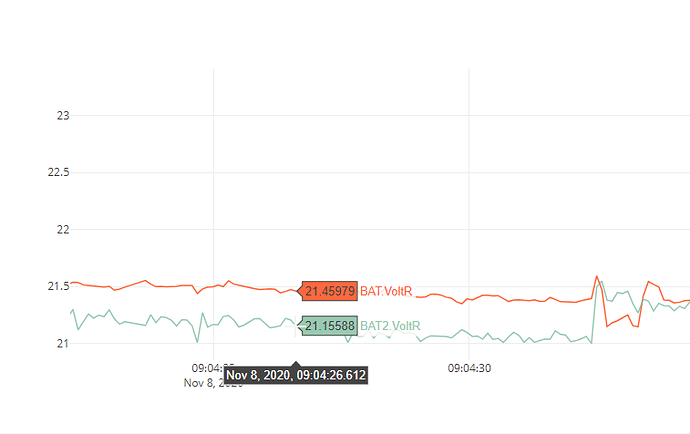
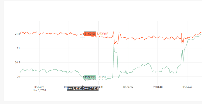
Now the low voltage failsafe I understand as I can see the 20.17 volts…but here is the problem. Failsafe is supposed to be set off by the Sag compensated voltage bat1.Voltr and that never got low enough to set off the RTL…
If you look at this graph you can see Bat1 volt versus Bat1.Voltr (RTL Voltage)
So I am pretty sure that my Bat1 voltage multiplier is off slightly and I will tweak it. But it doesn’t explain why the craft went into RTL on the wrong voltage measurement.
BATT_FS_VOLTSRC: Failsafe voltage source
Note: This parameter is for advanced users
Voltage type used for detection of low voltage event
Values
Value Meaning
0 Raw Voltage
1 Sag Compensated Voltage
The Y axis vibrations seem to be the same for you. I have a theory on mine. The mount for the flight controller is rectangular in shape going in the X axis. So I am wondering if the Y is too narrow and needs to be wider. Not sure I have the space for it to be wider.
As for the use of the graphing tool. It just doesn’t seem to work for me. I can’t find a ground speed like you have. I can’t get the compass to work out like you do. It’s very frustrating.
Even if I try graphing the mag field using the SQRT formula you gave me gives me different results…grrrr.
Can you tell if the compass is working better now that I ran the calibration at the field. I just can’t get it to work. I know it’s between the keyboard and the chair.
Hi,
From my limited knowledge I think your compass looks great!
The computed value (SQRT…) is pretty constant independent on the position/orientation of the aircraft and thats good.
The RTL from voltage maybe some from the dev. team can answer
Thanks Patrick
I think I figured out the RTL issue. I notice that the Sag Compensated voltage also went below the minimum voltage and did so for 15 or more seconds. This is what is required for the RTL to kick in.
So mystery solved.

