I am trying to integrate the Mauch 031 Power Distribution board with my Pixhawk Cube Orange (HX4-06159). There is a related post here but it doesnt look like any resolution was identified
While I have had success setting up the voltage, I have been stumped on the current sensing setup.
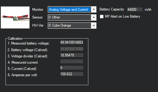
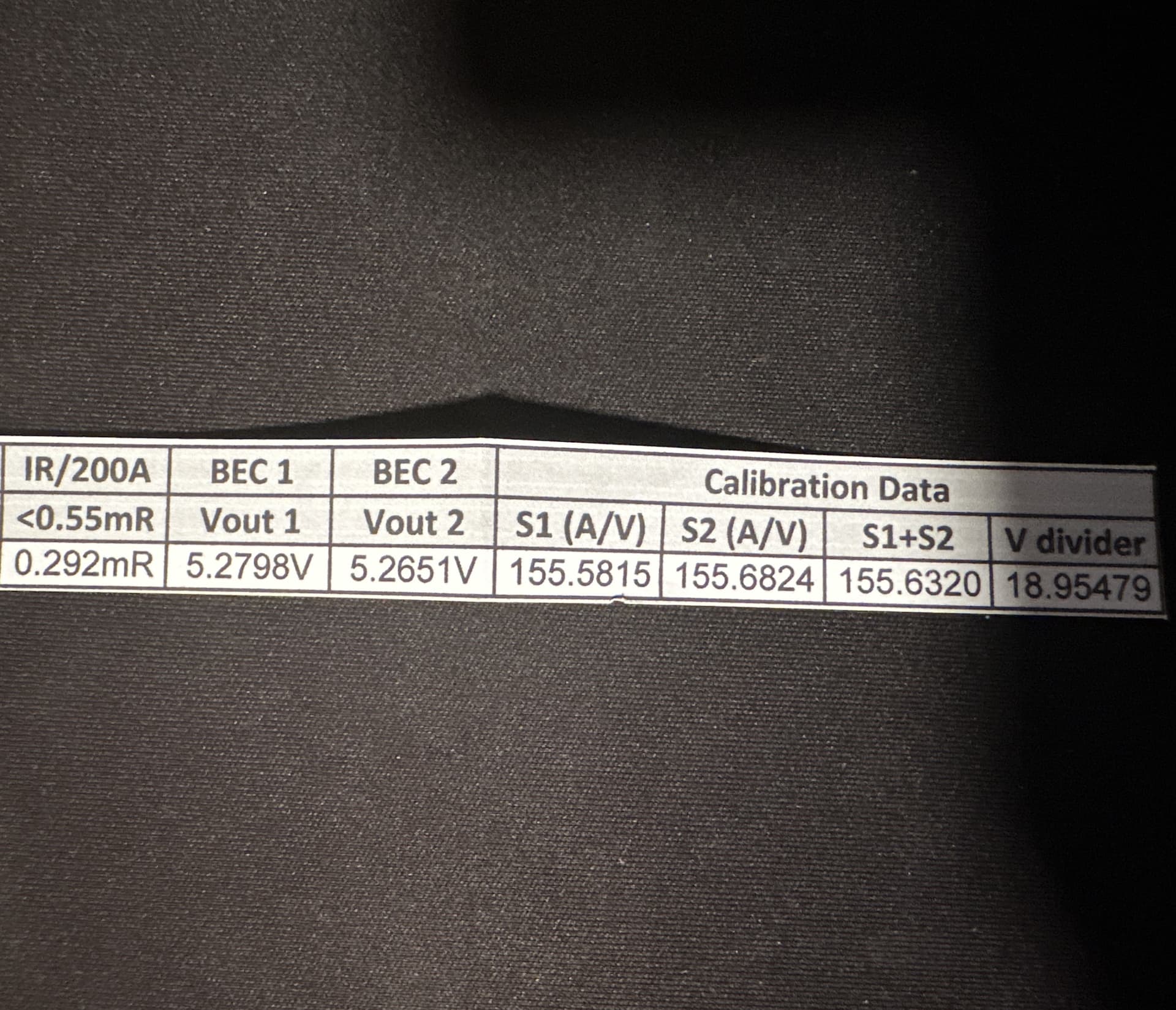
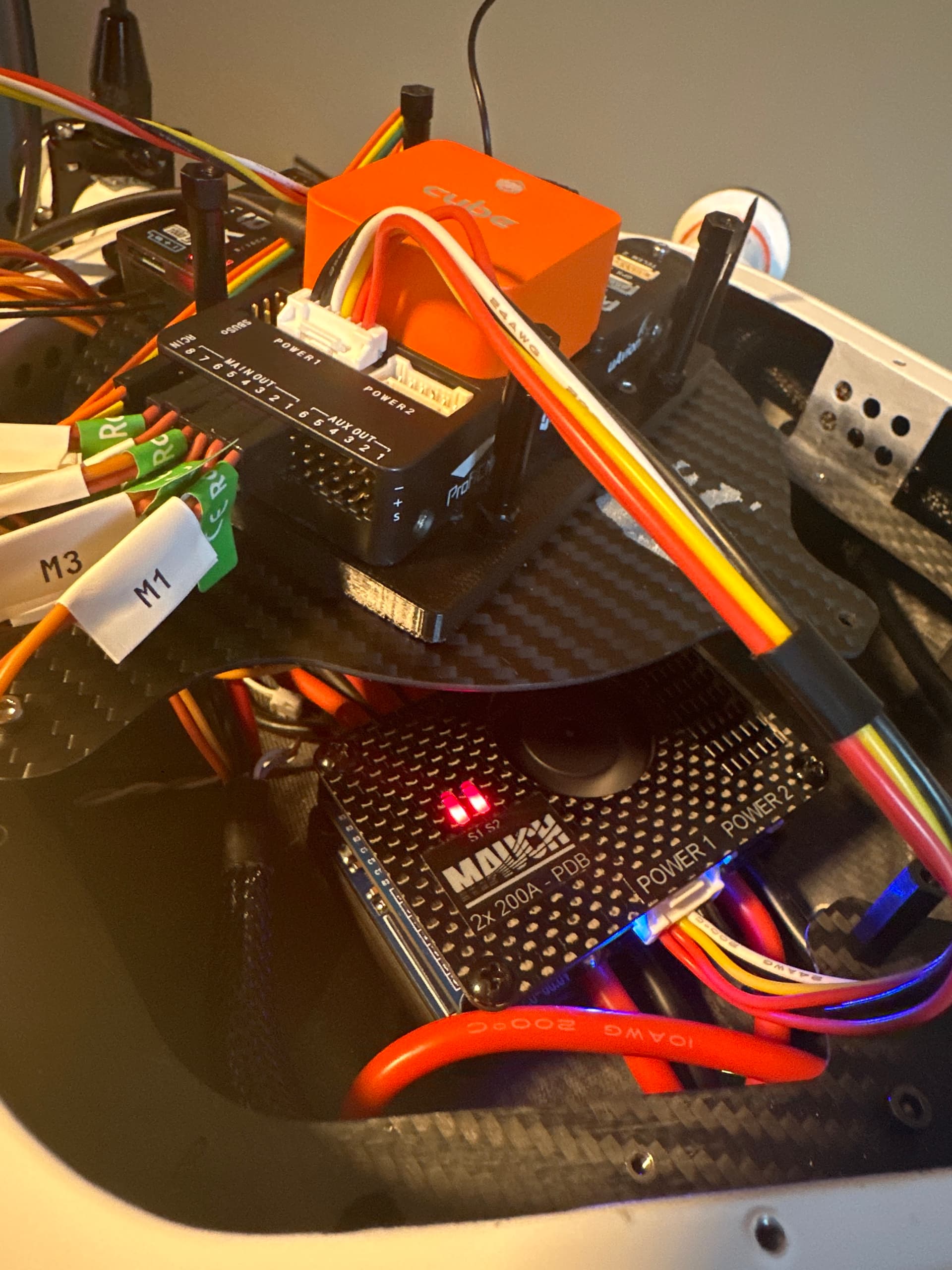
I am not sure where I am going wrong. I have everything configured and assigned the calibration values given to me in the Mauch packaging. I have a screen shot below, my parameters file, and an image of how I have everything connected to the pixhawk.
I am running on a single input at 50 Volts. I have the Hub X2 disabled by inserting the dummy connector. I am following instructions from this website
When I arm and begin to spin the motors I do see the current begin to increase, but SO far off from what it should be (a factor of 10). I also attached the calibration values given to me from the manufacturer.
Is it possible that the pinout is off for the connector from the Mauch PDB? I did take a look at the pinout for the CubeOrange here and everything looks to be wired appropriately if you compare the setup image with the pinout for POWER in the link.
Hey I found this manual that talks about the LED status. According to it the solid red indicates that you successfully are either using the switch or bypassed it. Do the lights turn green when you start spinning the motors? In which direction is the current off? Motors spinning w/o props draw very little current. Another thought. With the 200A limit and that A/V ration I’d expect the possible voltage range to 3.3v for that signal. If instead the cube is receiving a 5v signal range then that would have a dramatic effect on current. At the end of the day you can always do your own validation by measuring the current through the DC input as well as measuring the voltage of the current pin to make sure that the voltage is varying w/ current. You could also ignore the manuf. A/V ratio and just set your own with that measured current field. This page says it shouldn’t matter how much current your pulling with the Mauch’s but I’d still run the calibration with at least 5A being pulled. Power Monitor/Module Configuration in Mission Planner — Copter documentation
Thank you David. The lights are both red (as expected) as I am bypassing the alarm, I am running on a single input so I attached the dummy connector. As for what color they are when I spin the motors I am not sure but I will dig into this tomorrow night and report back here!
Sorry, a lot of distractions the last couple of days. I have an update:
When spinning the motors, the LEDs remain red. This is expected since I am bypassing.
I tried to do my own calibration and the current seems inaccurate at the lower current levels. I know that this is true for most power modules but there is an information block that the Mauch sensors are accurate at the lower ends for current.
I guess, really, the problem is that, at low currents, I get a zero reading but hall effect sensors are supposed to be accurate at lower current levels. I am currently drawing around 1 amp idle, so why is the FC not measuring that current correctly?!