I have a dual antenna RTK gps that provides true heading in GPHDT sentence. Is this usable in ardurover to eliminate need for compass ? How ? The other option I have is to use this data to simulate a I2C compass in software and feed this into the compass port as a pseudo compass. Any suggestions ?
If it’s otherwise working well, I think you should be able to set:
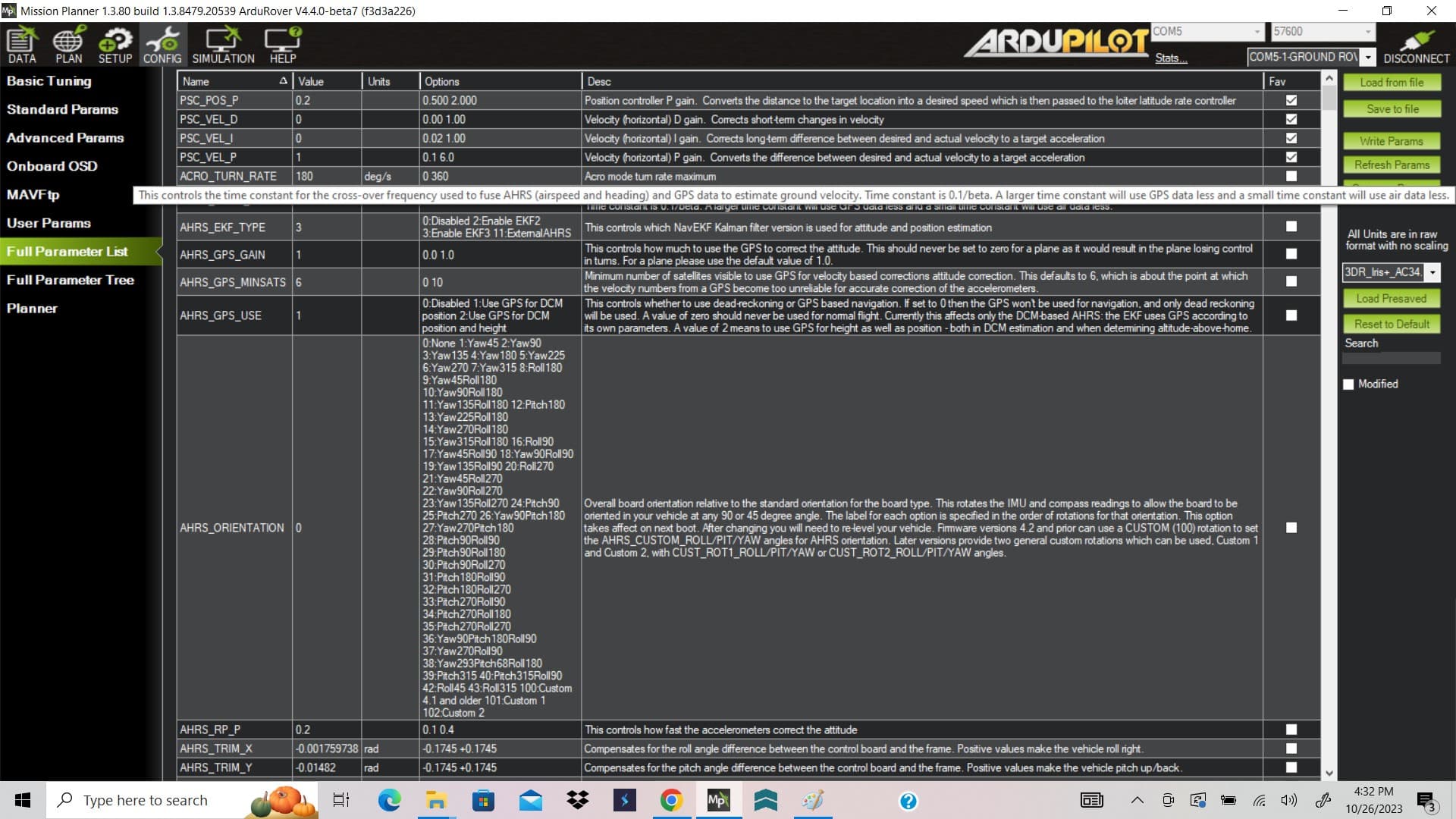
EK3_SRC1_YAW,2
GPS_AUTO_CONFIG,0
GPS_AUTO_SWITCH,0
GPS_TYPE,16
And get results.
Thanks for this help. I have been following your blogs closely and you are a great inspiration. I have 3 rovers:
- TINY : based on Thumper Frame - 2Kg
- SMALL : based on a SuperDroid chassis - 30-40 Kg
- LARGE : based on ICE tracked dumper 800Kg
I use TINY and SMALL to develop LARGE which is used for vineyard operations.
The GPS YAW works well. It is dead stable +/-0.2deg. Position is RTK-fixed and good to a few cm. So that is running well.
Now I upgraded to 4.4.0 beta on OrangeCube+. Rovers are all running correctly (no trivial task!) and now I want to tune the steering and throttle. I loaded the quickTune lua and will start once it stops raining. Any tips ?
Next GPS nav tuning using the new S-curve method.
Finally BendyRule obstacle avoidance using LS45B
Any comments and help appreciated.
NO joy ! It is reading the NMEA sentences as I get the correct gpsyaw value And it changes correctly as the vehicle is rotated. Precision is great +/- 0.2 deg. Position accuracy 7 decimal places or better. BUT a incorrect heading is displayed on the HUD. Changes, but does not follow the gpsyaw in any constant way. With this mess it is impossible to tune the steering (in ACRO) as the vehicle heading is just arbitary. On hard steering input in ACRO it just goes into an endless spin. In MANUAL it is controllable. I set the 4 GPS parameters as you suggested. No compasses are enable. There is only one GPS.
Stuck. Any ideas appreciated.
Provide a .bin log.
.
I can do that, but perhaps it is easier to look at data to first get the yaw to work. I see you have helped others with this in earlier blogs. I tabulated gps_yaw vs yaw and found there is constant difference of 210 deg. If the gps_yaw is say 82 yaw is shown as 292. I understand the GPS_POS is the adjustment but how do the X and Y relate to rotation ? Just trial and error ?
Antenna position relative to vehicle center (usually CG).
Since you’re using a system that isn’t fully supported, and you also refuse to supply any further data, don’t know what else to tell you.
OK. Thanks for your time. The RTKGPS provides heading irrespective of the 2 antennas. The GPHDT heading is relative to the axis on which the antenna are placed. In my case the antennas are exactly on the forward-rear axis of the vehicle so the angular offset is zero.
I worked with ardupilot 8 years ago and I never got it to get to work consistently. I went to other projects and just returned to the rovers. I got new equipment. Read up all the documentation and blogs. Decided to start with a simple thumper with 8n8 gps compass/gps. I got the tuning done and then was making progress with auto tuning. Then nothing works anymore. In AUTO mode it does not even start to go in the direction of the first waypoint. The bigger rover with RTKGPS will not align yaw as detailed earlier. Just spins around in ACRO mode. This is the sad story of my experience with ardurover and I will not waste more of anyones time and just abandon the project and toss everything into junk before it drives me crazy.
Well it sure sounds like you were close to getting something working. I just can’t help you if you don’t provide the requested info…
Spinning in circles usually isn’t a yaw reference problem so much as a motor configuration problem. If you started futzing with radio channel reversals to get it to drive in manual mode, there’s a good chance it’s not configured properly for autonomy. Search around here for related topics and you’ll see just how common that mistake is.
Thank you for the encouraging words. I will take a break from this project and hopefully will see you on the other side someday.
I took some time off and try again with clear head. Rover is 6-wheel thumper. Ardurover4.4.0-beta7. Motors are configured so no reversals are needed in MP. However throttle servo is reversed in the RC transmitter otherwise fwd stick = backwards motion. Driving good in MAN. Had to adjust MAX_SERVO and MIN_SERVO to track straight. Drives good in ACRO with similar behavior as MAN. When I switch to AUTO the line to WP1 is correctly shown on MP. L1 controller parms are greyed out (I assume due to > 4.2). The S-curve parms are set to
I know you want logs but if I connect via USB I get getlogentrytimeout. If I connect via telemetry I get a list of files but to download any of them is impractical as it would take hours for just one. I apologise but I just cant download these logs.
The problem is that when the vehicle is pointed directly at WP1. Moving it in acro back and forth shows the heading to be pretty much lined up and the left and right servo values moving together. BUT when I put in AUTO left servo goes full reverse and right servo goes full fwd. They should both have gone full fwd to go towards WP1. I thought that if ACRO works then motor configuration is correct to for AUTO. It will also not do CIRCLE mode correctly. How to test and fix ? Any help appreciated.
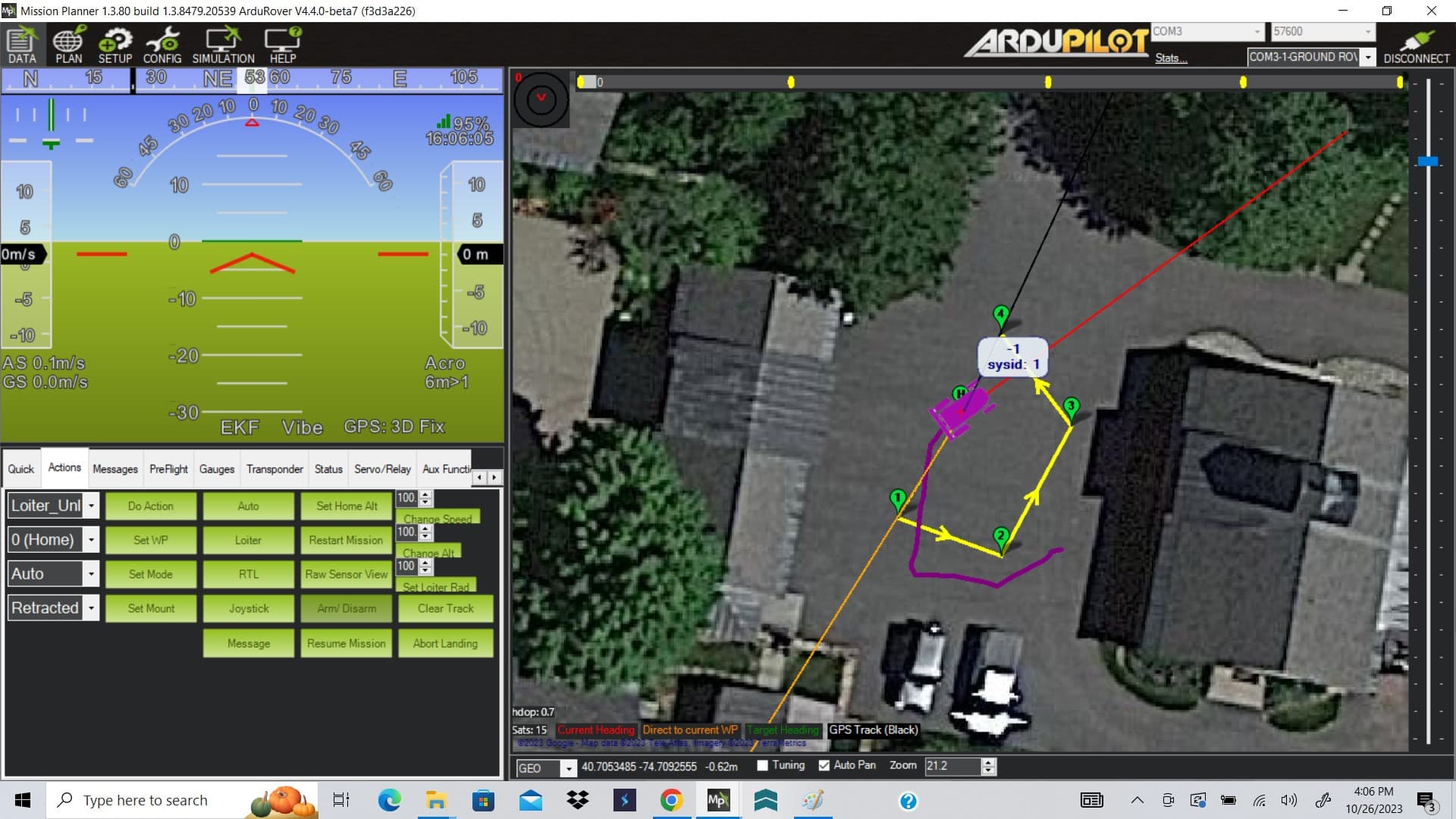
The after AUTO note the rover starts to turns away

Update - I upgraded to ardurover 4.4.0 beta 8 and Voila the log files can be accessed and uploaded via usb. Some bug in beta7 I presume. Now I just have to figure out how to upload it here since it is too big.
OK. Some progress. I downgraded to the 4.2.2 stable release. Both my tiny and medium rover can now perform auto circuits. You were right - it imperative to get the motor right. The motor test facility in MP is the ticket. Nobody should do anything unless they get this to work correctly. On to Bendy Ruler. I will open a new topic. I have it working with SF45 lidar and I see circles on MP. The one thing that puzzles me is why the rover width is not a parameter ? After all a 2ft wide rover can go through an opening that would be too small for a 4 ft wide rover.
There are margin parameters for that.