Should be fine. A bit heavier and more power than other setups but it should work fine.
Hi @GregCovey I really enjoy your conversations and I learn a lot from this forum.
I recently bought Nimbus Kit from FOXTECH and I build it piece by piece. I have some issues with servos. When my motors are working on high speed, I hear strange sounds from my servos. See the following video.
I use UBEC 5.2Volts to power my servos.
Let me know if you ever had such issues.
Any advice?
Thank you
Hi Petrou,
Welcome to our Nimbus VTOL thread!
My initial guess is that the servos are trying to yaw. Typically, I don’t test transitions on the ground while armed. There are speed estimators and yaw compensation that do not work well on the ground, so I do it while unarmed and the motors off. Your yaw compensation will get tested during the hover tests.
Also, your 5.2v UBEC seems low. We typically use 6v-7v for increased torque.
Cheers!
1 Like
Hi guys,
I have install on my Nimbus VTOL (grey version) an external gps + compass module which works perfectly.
I also bought a digital speedometer from Foxtech and i connect on a I2C splitter with compass.
I’m using Qgroundcontrol for the configuration and setting the ARSPD_PIN to 65, the option ARSPD_USE to 1 and ARSPD_TYPE to I2C-MS4525D0. But I don’t see any data related to airspeed on the interface.
It detects the sensor and I get an error message about speedometer health.
After a while I noticed that it was very hot!!
Has anyone experienced such issue?
Thank you
1 Like
Hi Vasos,
You are our second new poster today, so welcome! 
The AS Sensor should not get hot so this is why you do not see a proper display in QGC. I suspect the IC2 wires are not matching the others.
You can display the AS sensor value (when it is working properly) without actually using it in your first flight. In fact, this is the preferred method so that you can chart the log and validate operation before using it for flight control.
- Set ARSPD_USE = 0 and ARSPD_AUTOCAL = 1 for the calibration flight.
- Verify operation in flight log.
- Set ARSPD_USE = 1 and ARSPD_AUTOCAL = 0 if good operation
2 Likes
Hi: Welcome to the Nimbus Tricopter VTOL thread.B.K
Hello Everyone!
I’m getting on with the build of Nimbus VTOL and will keep sharing the progress here.
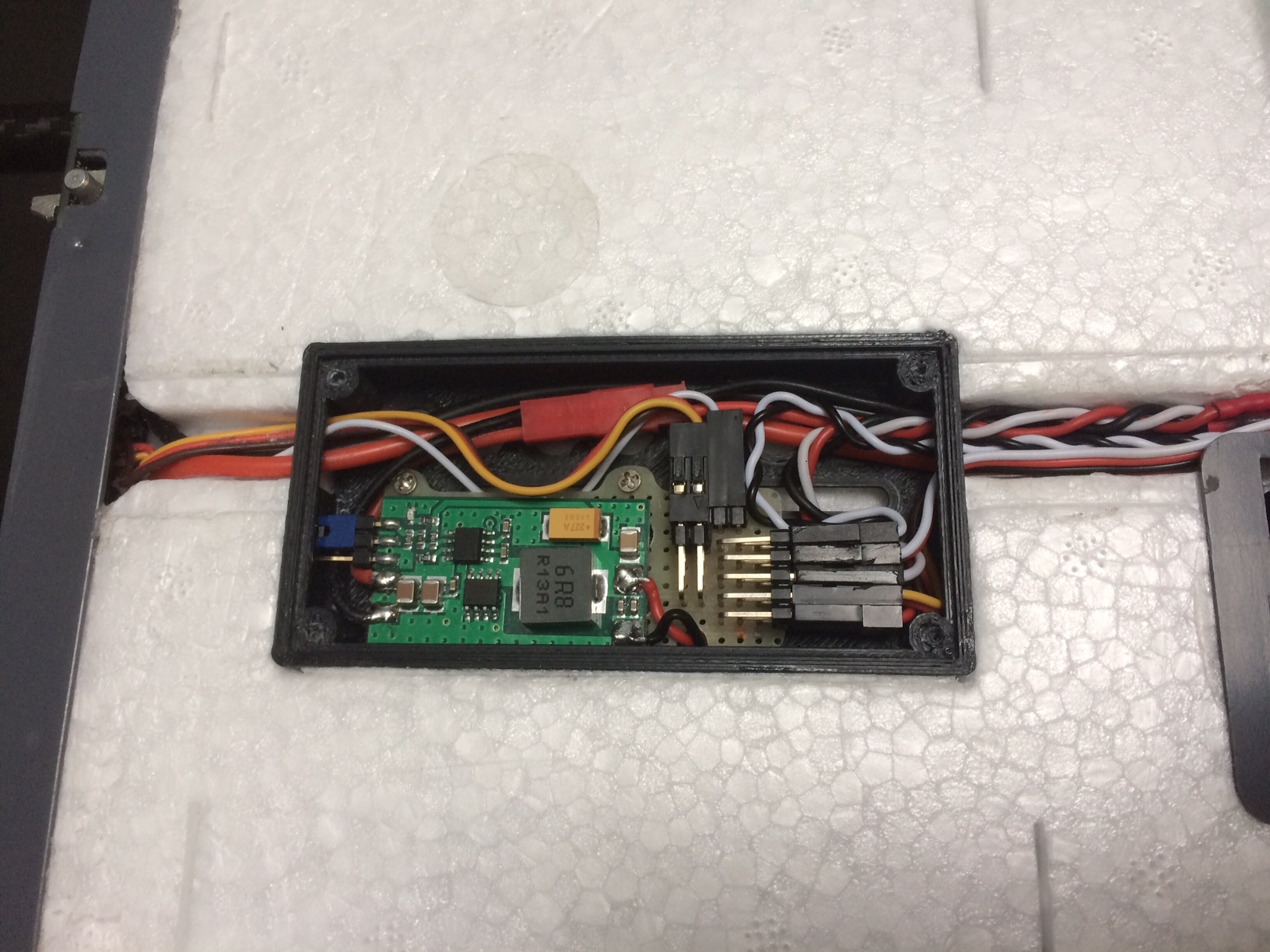
First, I was a little disappointed to see 16 AWG wire going to the bullet connectors on each wing and also by the wire gauge used for the servo cables. I decided to take a look at the wiring quality inside the wing as well and removed the plastic covering underneath the wing. Here is what i found:
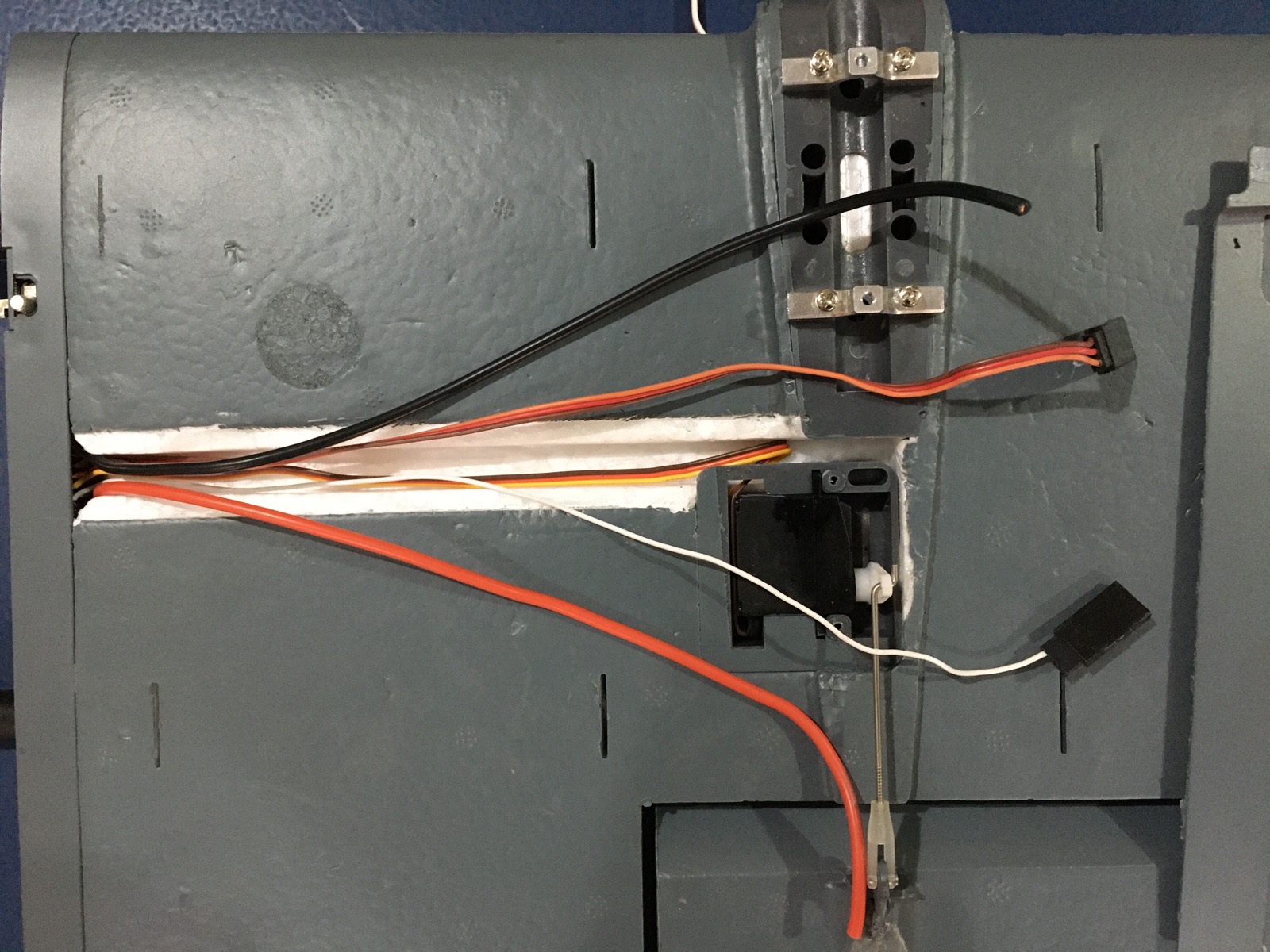
Same 16-AWG wire for the Motor, and a signal wire (white) without a ground for the ESC.Now I can appreciate the extra effort done by you guys to up-grade the wiring. Unfortunately, I am not much experienced with cutting foam and adhesives that work with foam and stuck with whatever is in here 
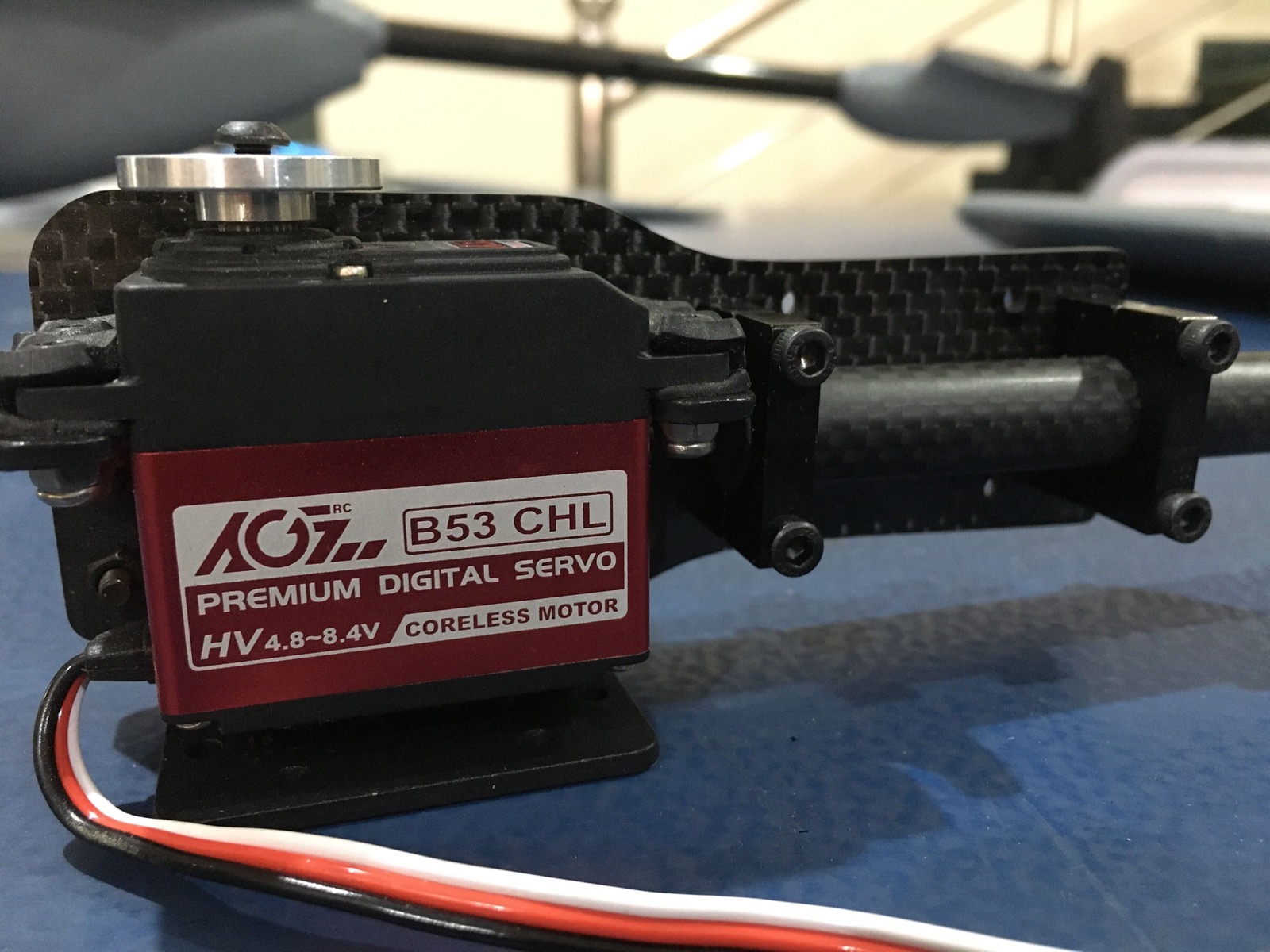
The tilt mechanism uses a B53 CHL servo supporting 4.8-8.4V.
I have a single 10A Hobbywing UBEC with selectable voltage up-to 8.4V. I am wondering if it would be OK to use a single UBEC on the Pixhawk 2.1 servo rail (Servo rail supports up-to 10V) to power all the servos. I have seen in the thread that many of you are using dedicated BECs in each of the wing to drive the Tilt Servo and a separate BEC for the Tail/Aileron. It seems much safer option but i am not sure if i would be able to cut the foam to make room for BECs under the wing without damaging and alter the wiring.
I am looking for a re-assurance from someone here who is using the stock Nimbus wiring with a single UBEC without any issues. Please advise if I can proceed with this wiring or alteration is a must.
Many Thanks
Hi @AM_AVT,
I use ASSAN UBEC 8A to power my servos on the Pixhawk 2.4.8 power rail.
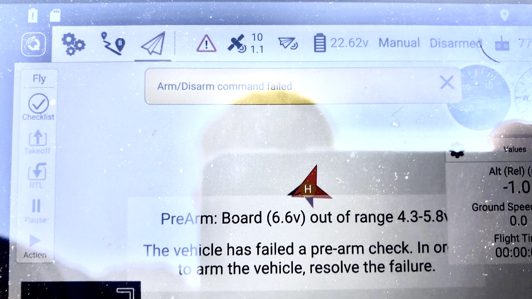
I try to power with 8.4V but I get an error on my QGC with a message for out of range (4.3-5.8V).
I switch UBEC to 5.2V and works, but as @GregCovey said, it is very low. Need to power at 6-7Volt to achieve torque.
Hi @Petrou_Savvas,
This is because of the input voltage specifications on the Original Pixhawk and applies to Pixhawk 2.4.8 as well which is built on the same power architecture as per my knowledge.
As pointed out by the documentation, the Servo rail is being used to power the Pixhawk FMU itself in the Normal Mode and that is why the absolute maximum voltage is limited to 5.7V in this mode.
However, if you are using a separate Power Module and do not want to use the Servo Rail to power the Pixhawk FMU (or act as backup power) you can use the 8.4V BEC to power the Servo Rail as per the ArduPilot documentation page on Powering the Pixhawk. Please note that if you are using a BEC with higher than 5.7V output, you MUST NOT use the Zener diode.
So, using a Power module for the Pixhawk, and 8.4V UBEC on the Servo Rail (Without a Zener Diode) should solve the issue.
Cheers!
CAUTION: Pixhawk 2.1 uses the voltage applied at Servo Rail to power the RC receiver as well. So when using a higher than 5.0V BEC make sure the RC receiver can support the same voltage as well. I am not 100% sure if the same applies to Pixhawk 2.4.8 but you can check using a digital volt-meter
1 Like
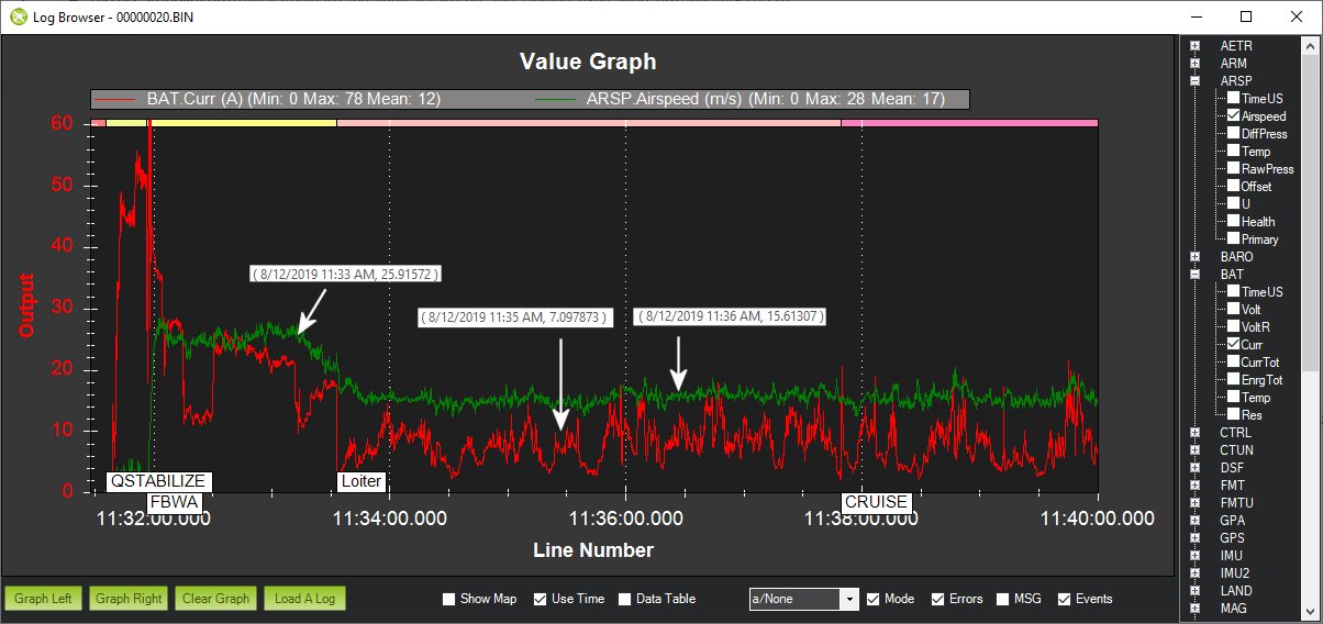
Hi Amir. You can see my flight data. My Nimbus flew 15 km. and this is not the limit. Battery capacity is 12 Ah
2 Likes
Hi Aleksandr,
Thank you for sharing the log. I see around 16A average current draw from entering CRUISE mode to switching back in FBWA. What is the AUW with 12AH battery pack. Also, are you using the SunnySky 3520-520KV Engines and what size propellor?
Thanks
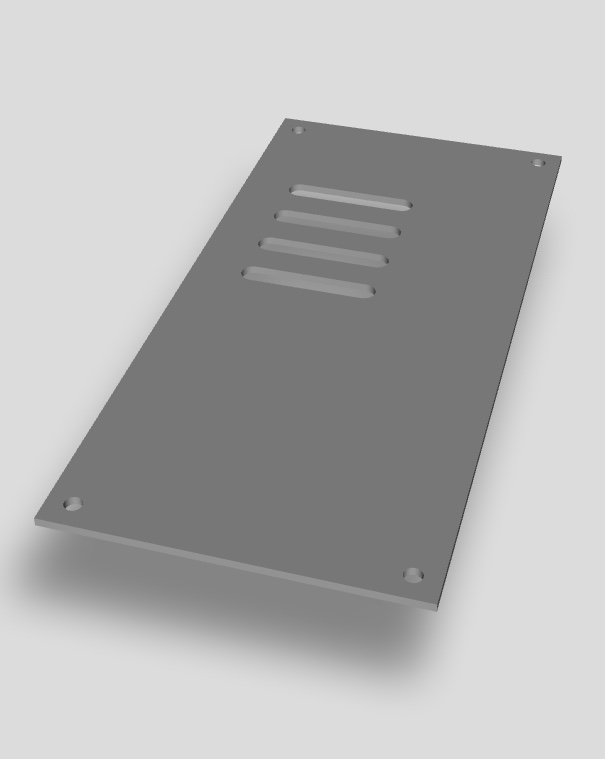
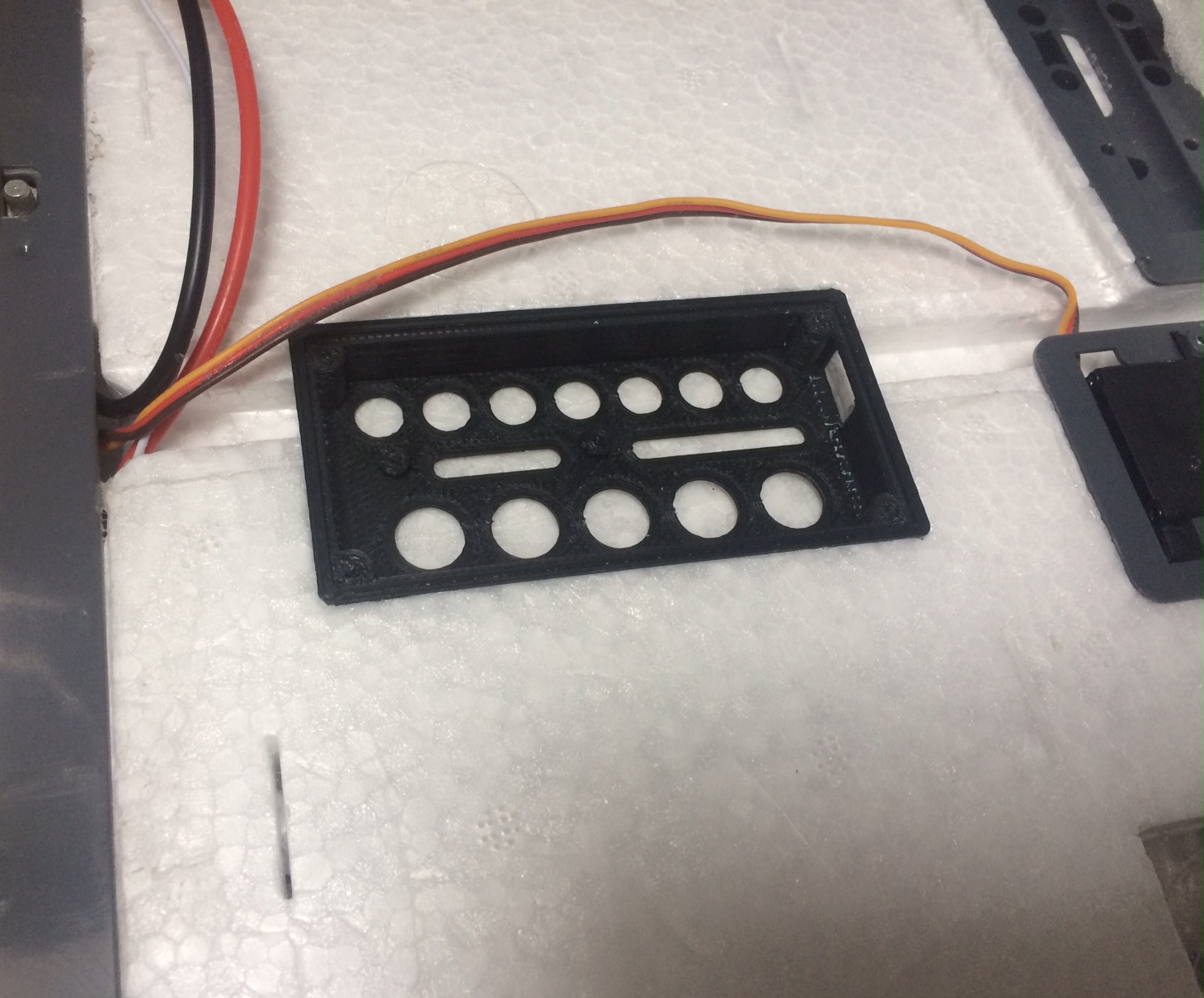
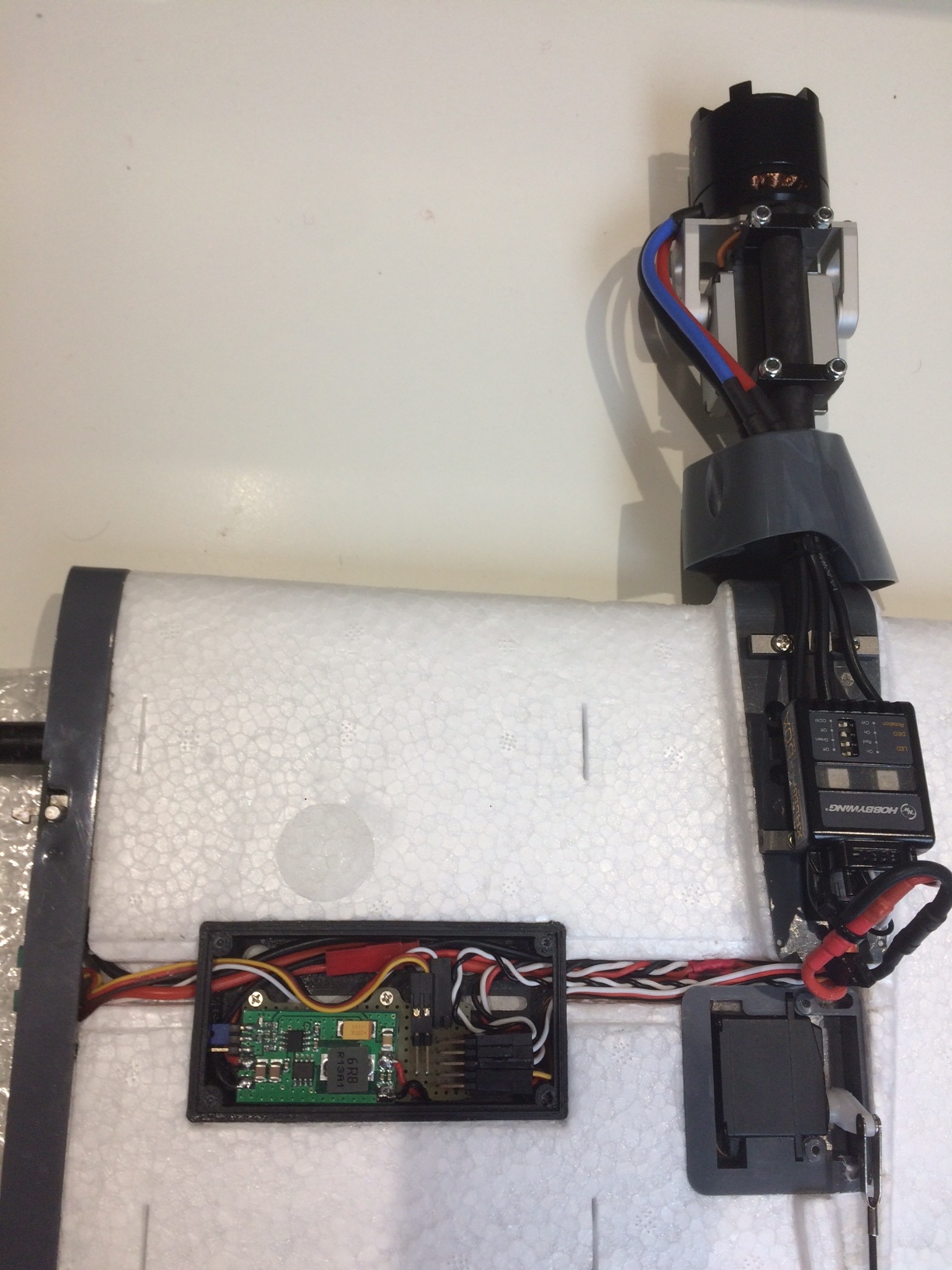
AM_AVT, I decided to embed one 3D register on the intrados of each semi-wing. It is not excessive weight and is more advisable.
Registro_BEC_alas_Nimbus(1).stl (146.8 KB) Registro_BEC_alas_Nimbus_simetrica.stl (146.8 KB) Tapa_registro_BEC_con_nervios - .stl (63.9 KB)

2 Likes
Hi Atico,
That’s a Brilliant modification 
I’m a little hesitant to cut the foam as this is my first time dealing with EPO. I will get the parts printed and try doing the mod. Wish me Luck!
Thank you
Hi Amir. I use 13x8 propellers Greg gave a link to them. Don’t understand the battery issue? The engines I have are like this: https://aliexpress.ru/item/32507818703.html?spm=a2g0s.9042311.0.0.264d33edOkeEOk
Beautiful and successful flights!
All,
Here is a current and airspeed graph of my Nimbus for comparison. My Nimbus is fully loaded with a 2-axis gimbal and camera up front and an S100 camera below. I was using a 6s 10AH Multstar LiPo pack and SDP33 AS sensor. The average FF current seemed about 7amps in autonomous modes with an AS about 15m/s. The higher hover currents in QSTABILIZE mode were due to ascending on take-off.
Hi Atico,
I hope that you, your family, and your Nimbus are all still safe!
Cheers!
1 Like
It is an excellent current.
Everyone in good health,
thanks
Hello friends,
I have finally been able to finish my article about Nimbus VTOL. Home confinement for the Covid-19 has given me time to finish it. I hope to collaborate.
SHARING WE ADVANCE
Health for all
5 Likes
Atico,
Very well done! The Google translation also seems to work well for making it English.
How do you like the Pixhawk 2? For hobby use, I have always used Pixhawk 1 (a.k.a. v2.4.8) since it is much lower cost.
Cheers!
1 Like
well, the Cube improves in redundancies mainly and it could also be that it had less “strange problems” than with the pix 2.4.8
1 Like
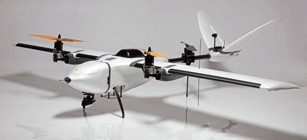
@Aticof Beautiful build, love the avionics stack very clean!