Greg:I also had a question on the wiring diagram for the ubec ,it looks like the motor tilt servo sig wire is getting connected to the power wire of the ail servo wire if so how does the tilt servo get signal?Thanks B.K
Butch,
I don’t see anything in the param file that looked wrong. I would focus on a hover test using QSTABILIZE mode first and then QHOVER and QLOITER once QSTABILIZE seems ok.
Don’t use MANUAL mode as that is for normal planes. The emergency go-to mode on a VTOL is one of the three Qmodes above. My preference is QSTABILIZE since I always have it as the most clockwise position on my Taranis or Horus transmitters.
On the UBEC wiring, don’t let the wire color fool you. The existing stock red wire that runs through the connectors is re-assigned to the tilt servo since it is no longer needed to power the servos. The servos get fed directly from the UBEC now in the wing. This re-assignment has to be accounted for in the main chassis.
Good luck!
I switched the tilt yaw parameter from 30 degrees to 13 degrees. On startup the motors go to a 90+13 degree angle, is this correct?
Or should it just be 90 degrees and I should mechanically adjust the servos?
I don’t know why this is so confusing for me!
Greg: Thanks just being sure about the wiring i don’t like the smell smoke
I don’t know how others are setting this up, but in my case I make it go straight forward for plane modes and 90 degrees up for vtol modes. Once I raise the throttle, the servos start to move in vtol modes. I have my tilt yaw angle set to 20 degrees since 13 did not have enough authority in light winds. now I can have it sideways in 10m/s wind with no prolem.
I agree with Romeo_E on how he set up his Nimbus VTOL. The 13 degrees came from the FoxTech setup and seems to work fine for most of us because it provides a 26 degree swing on each tilt-rotor.
Here is a diagram posted by Rolf and some description by Tridge that may help your orientation.
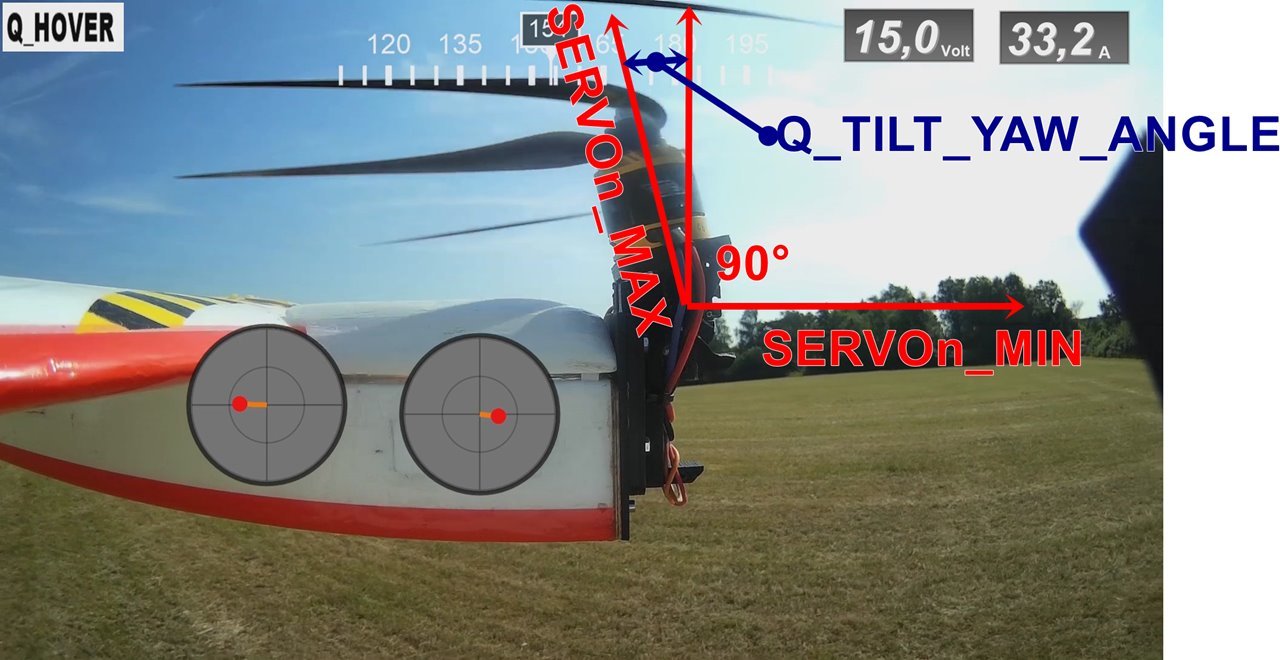
I admit it is a little confusing, but it should be like this for simplicity:
- set q_tilt_yaw_angle to 13 or whatever works for you
- upon power up (not arming) the servos should be 90 degrees up (the firmware works out the difference between max angle and straight up)
- if motors not straight up adjust max_servo until you get there
- upon arming and throttle up (without props) you can move yaw stick and see the motors tilt
This is how I do it.
Between Romeo and the Pic that Greg posted I was able to get her to work!! I was doing motor testing when I saw that the right motor servo likes to “twitch” all the time, please see the video and tell me what you think:
I’m guessing noise on the line?? Bad servo? Can I ignore this?
Everything is tight so it’s not a loose mechanical anything…it’s 100% coming from the servo itself.
If the Rx antenna is close to the servo wire try to move it and see if it cures the twitch. Otherwise I would not fly with that servo.
It’s an odd twitch on just the right side. Does the same servo also twitch when facing forward?
Can you plug in a servo tester at the servo cable to see if it is the servo or noise on the line? It might save some work if you don’t need to remove the servo. Even a cheap one like this $4 Servo Testor from HK would do the trick. I keep one in my flight box and one on the bench.
If it is noise, then you’ll need to move the servo wire around a bit. I would start from the Pixhawk end.
Good luck!
Hi Greg: while waiting on a few Parts, speed sensor,servo rod quick link,I wired the wings as per description then wired up the pixhawk now thats were i’m having a prob, the wing wires are joined together into a Y cable so do i split them and make cables for the FC cause their is only one esc wire for only one motor? Thanks B.K
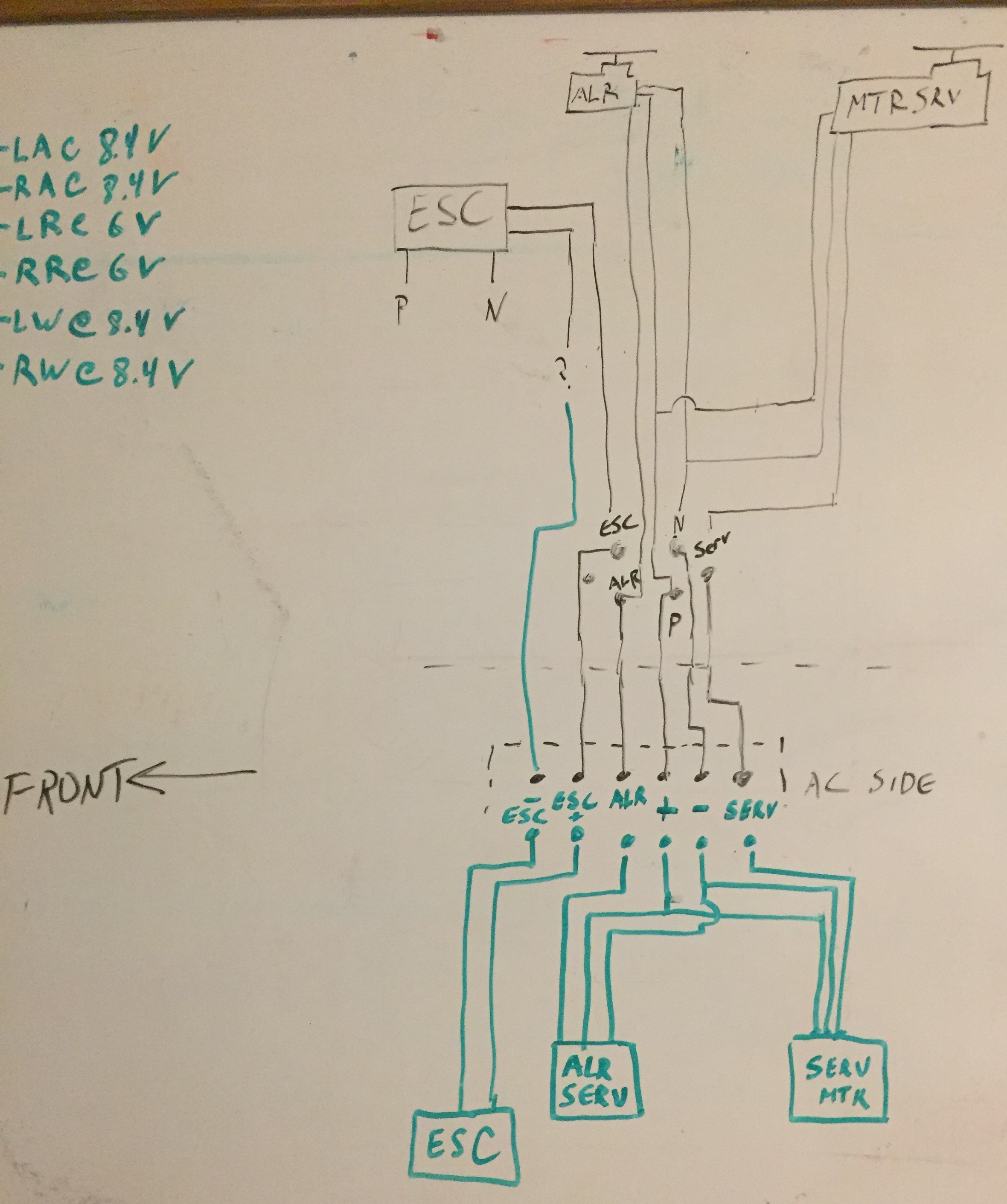
@Butch Yeah, I stripped out ALL of the factory wiring and ran my own, this required splitting the tail section open to gain access. I did this because the factory wires are not exactly good quality nor do they carry the ratings to use 2S servos (I replaced all of the e-max servos with 2S servos) amp wise. You will also find that the factory guys are fond of running a single signal wire instead of both a signal and a ground wire. In my experience that is a great way to cut down on expense and a some weight but it’s also a great way to introduce a single point failure when the ONLY ground wire you have attached comes loose. When that happens any connection without its own ground will cease to function or not function correctly depending on how the rest of the wiring system interacts.
Here is what I made up to guide me through the re-wiring process in case you want to give it a go:
1 Like
Motor Servo Twitch SOLVED:
Greg was right, it was noise. It is noise being induced into the signal wire of only that servo and its coming from the RFD900x that is about 23 inches from the servo itself to the base of the right side 900Mhz antenna, or another measurement is that the servo wire end (that is plugging into the back of the Pixhawk 2.1) is about 10 inches away from the same base point on the right side antenna.
I can verify this by covering the 1W output 900Mhz antenna with my hand and the pulsing stops (I assume its pulsing because of the heartbeat function?). I can also make it stop by pointing the antenna straight down the fuselage towards the tail and thus the servo wire is getting the shadow of the dipole antenna.
What is weird is that the same is not happening to the other side of the wing! RFD has diversity reception and some form of output so I unscrewed the offending right hand side antenna (right side referenced as if you were sitting in the cockpit of this drone) thinking that the output signal that was causing the noise on the right side servo would stop (and it did stop) and pick up on the left side servo (which it did NOT).
This leads me to the fact that due to the way the autopilot is sitting in the fuselage that the extra 6 inches or so required to reach the other side to be plugged into the servo rails is just enough and positioned just right enough to have this noise induced. I’ve basically turned my servo wire into an antenna.
Not sure how I’m going to handle it, I can:
- Reposition the entire RFD900 (which is not a good option for me)
- Fix the offending antenna into another 90degree angle (which means pointing it at the tail in which case I get an RF shadow due to the carbon fiber tube)
- Attach a ferule to the servo wire (band-aid to the problem)
- Take out the damn autopilot again and redo the cable management until the twitching stops (which may or may not work at all)
- Lower the power output of the RFD (umm. NO.)
- Find some pixie dust and sprinkle it ambley.
Any other ideas??
1 Like
Hi Greg:Thank You, Darn and i just ordered a spare set of emax servos when i read previous comments on this thread about servo problems,so what servos do you recommend what gauge wire and and where do you get the 8.4 volts from and how does that affect the Pix FC,AS you can tell i’m not the brightest bulb just a old retired Blue color SPED just trying to run alongside the big boys but dreams need to be pursued and Thanks again for all your help and wisdom i’m here to learn and i’ll try any thing it just takes me longer.B.K
Butch,
I just split the existing Y harness as in the original conversion by Kris. A thicker common ground wire is run for power to the ESCs and BEC which is fine for the servos.
It looks like Chad went the extra mile to replace wires and servos. After replacing my one bad Emax servo in the tail, I have not seen a problem since. You can always take the quick solution and then re-do things in the winter months.
Chad,
Your issue with the higher powered RFD900 is common. I had a similar issue on my APM Antenna Tracker. In my AT setup, I was able to move my antenna positions.
Another option for you would be to use the RFD900 at the base station only. You then use the normal 3DR style telemetry units on your aircraft. I did this on my setups because it is more cost effective and still provides a good 5 or 6 miles of telemetry distance. In essence, you don’t need an RFD900 at both ends unless you plan on flying a 25 mile (46km) range.
I don’t think attaching a ferule to the servo wire is a band-aid. It properly reduces or eliminates the RF field riding on the wire.
Good luck!
Thanks Greg: They Call My Wife and I Early Snow Birds we have already been in Fla for 3 weeks for the Winter so i really don’t have winter months only space constraints living in Good Life RV Resort And a Huge Area to Fly All to Myself. So while i’m reading your suggestions i also read your comments to Chad, i also have 3Dr telem,and was thinking of using my EZUHF or R9M where do You Put any of these on the Plane cause i was going to change over to one of these once or if i get this VTOL Tuned in seeing how the taranis X8R don’t have the Range ? Thank You again.B.K
Maybe try wrapping the servo wire with copper tape? This may also be available at your local music store.
Good luck.
Since the application of my bird requires as much reliability as possible I indeed went the extra mile.
The servos that move the motors are two AGF B53CHL 2S monsters that can pull up to 4 amps each under stall conditions and the stock E-Max servos will only handle a 5V power supply. I have no data on the failure rate of E-max servos but I HAVE had generic servos fail in flight and thus result in a 2 mile hike with a rented fiberglass 40ft ladder to the middle of nowhere to get the bird back (because, you know…birds love to roost on top of FRGN trees)!
Since I could not change the motor servos (they must be strong for this type of aircraft) and I did not want to add multiple BEC’s or possibly have to use two batteries (both options add complexities) I opted to do the surgery on the bird. Since it was laid open I also went ahead and replaced most of the factory wires. After all of that work it bothered me that some signal wires did not have the accompanying ground wires so that’s when I redid the wing wires and thus shed the last remaining aileron’s factory wires.
I use this table to determine if the wires are going to be able to handle maximum current load without melting. Granted, the likelihood of a servo maxing out long enough to cause damage is very very low but then again bearings can seize and other weird coincidental events can and do happen. I’m paranoid I guess!
The 8.4V comes from a Castle Creations Pro BEC. I’m not pushing this brand but I’ve never had a problem with them even in the Texas heat of 110degF. The Pixhawk 2.1 is rated to handle 10.5V max so there are no negative consequences for the autopilot.
I rarely fly out of line of sight but I have in the past under certain circumstances. The reason I want to keep the RFD on the bird is that sometimes you need the power boost in order to penetrate objects such as trees or you simply want to be the strongest 900Mhz in the area. I don’t always get an ideal place to fly. I’ll try the ferules here shortly once I find them in my stockpile of parts!
1 Like
Ok, I moved the wires a bit and put the ferule on, no more twitching (for now at least).
I’ve fixed all of the issues I know of, would anyone mind taking a look at my parameter list and see if anything obviously wrong is going on? This is an important build for me!
Nimbus VTOL V1.2.param (17.1 KB)
1 Like
Chad,
I can’t remember if you are just hover testing the Nimbus or plan a transition to forward flight as well.
If you stick to using only FBWA mode for your maiden forward flight, you’ll be fine. However, if you decided to use CRUISE or LOITER modes, I would not enable your AS sensor until it has been calibrated once. Rolf has recommended even doing this on the SDP33 sensor.
For first flights without an AS sensor.
- ARSPD_AUTOCAL,1
- ARSPD_SKIP_CAL,0
- ARSPD_USE,0
After a calibration flight of simply flying in CRUISE or LOITER mode for 10 minutes…then check the log for Air Speed vs. Ground Speed. If the results look reasonable then enable the AS sensor.
- ARSPD_AUTOCAL,0
- ARSPD_SKIP_CAL,1
- ARSPD_USE,1
If you are not carrying a payload, you could change your settings below,
- ARSPD_FBW_MAX,28
- ARSPD_FBW_MIN,14
to a lower value like these. This keeps the plane from flying too fast when the AS sensor is disabled and you keep the throttle at mid-stick. It will also transition to FF sooner.
- ARSPD_FBW_MAX,20
- ARSPD_FBW_MIN,10
Your flight modes have me a bit concerned.
FLTMODE1,19 (QLOITER)
FLTMODE2,11 (RTL)
FLTMODE3,5 (FBWA)
FLTMODE4,7 (CRUISE)
FLTMODE5,19 (QLOITER)
FLTMODE6,21 (QRTL)
As with any “copter” testing, the preferred method is to start without sensors. I use the flight mode sequence below.
- QSTABILIZE (Pilot)
- QHOVER (Pilot and BARO)
- QLOITER (Pilot, BARO, and GPS)
Once the copter testing has finished, I used this sequence below. When transitioning from a forward flight mode, it is (or was) considered a bad idea to change to QLOITER mode as the vehicle is stressed to stop as quick as possible due to GPS. I am not sure if that has changed but I never do it.
- QSTABILIZE
- QHOVER
- FBWA
- CRUISE
- LOITER
- QRTL or AUTO
Good luck!
2 Likes