OK, so you are saying the actual (externally) measured RPM is the same as the RPM logged in Ardupilot with RPM1_SCALING,0.5 ?
Is your tachometer measuring actual RPM or blade passes (double RPM for two blades) ?
Therefore I think for the harmonic notch filter to use that correctly you would have to set: INS_HNTCH_REF,0.5 (in fact 0.4 is closer to correct → see below) to halve the frequency that HNOTCH is currently thinking it should work at.
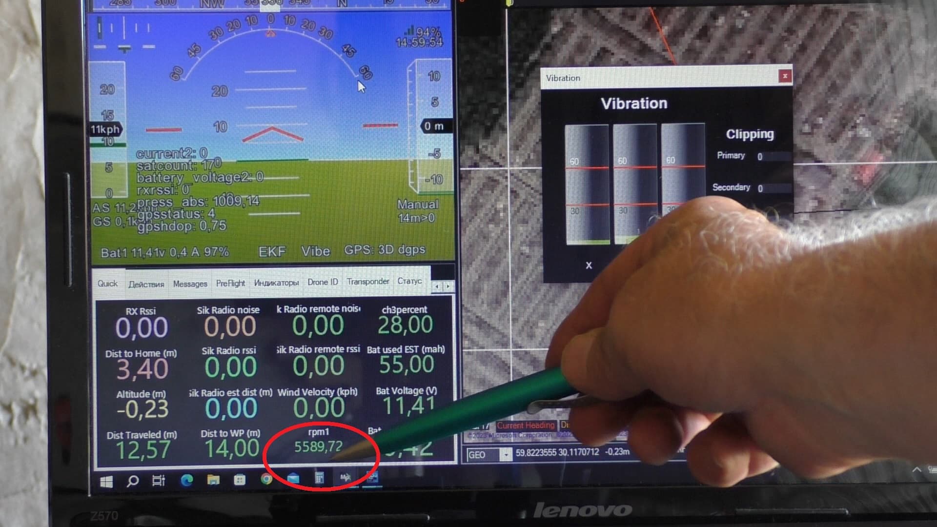
The tachometer showed the actual speed of revolutions, this coincides with the measurements of the Ardupilot RPM1. The tachometer measures two pulses per revolution of the propeller and scales a factor of 0.5. The speed sensor measures two pulses per revolution and scales RPM1_SCALING = 0.5.
This might occur in a geared drive train setup. This is not in my case, because the propeller rotates directly on the motor shaft
INS_HNTCH_REF this parameter, as I understood from the manual, is used if a gearbox is installed between the propeller and the motor, and for filtration it is necessary to measure the rotor speed
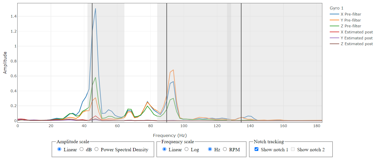
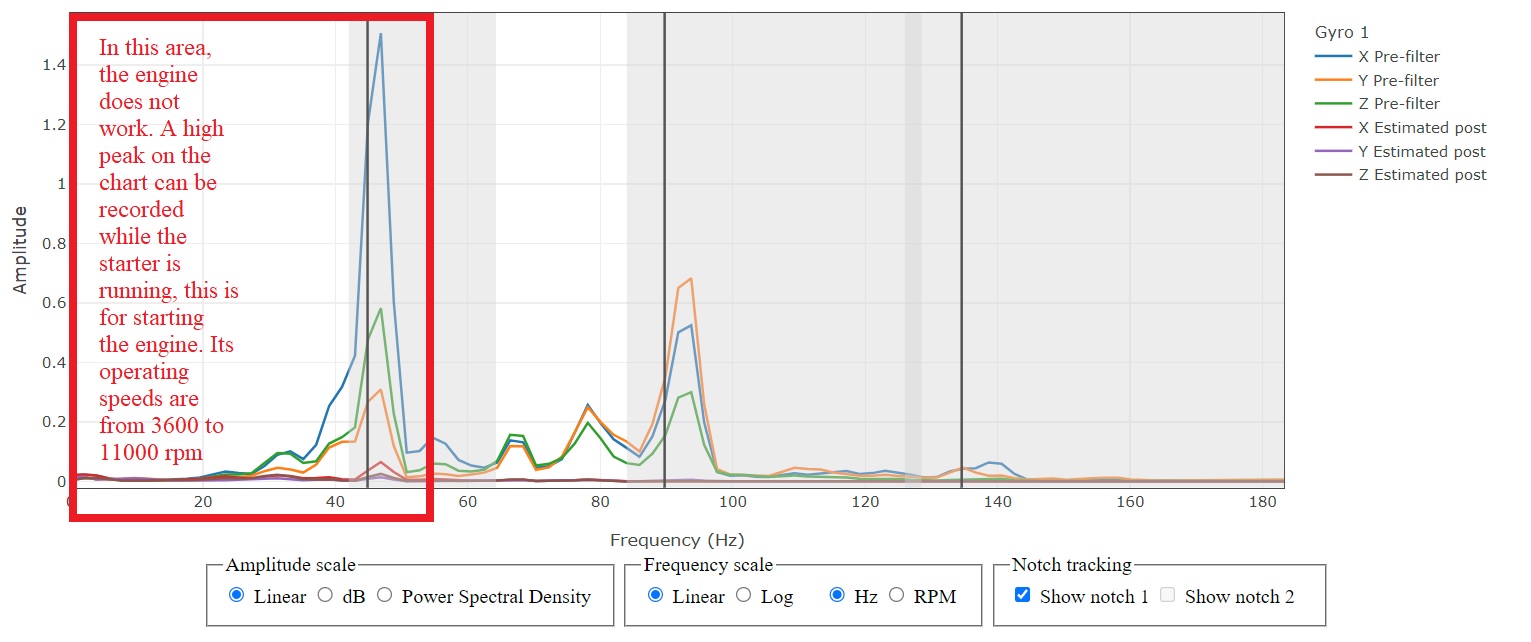
There is no working area on the graph in the selected rectangle, I think this will not affect the flight of the aircraft, because the operating frequency is 5400-6000 rpm, which corresponds to the cruise speed of the flight
Have you got a log of that flight with the HNOTCH batch data?
What’s causing the confusion is the logs provided and analysed by both of us is NOT with the plane actually flying.
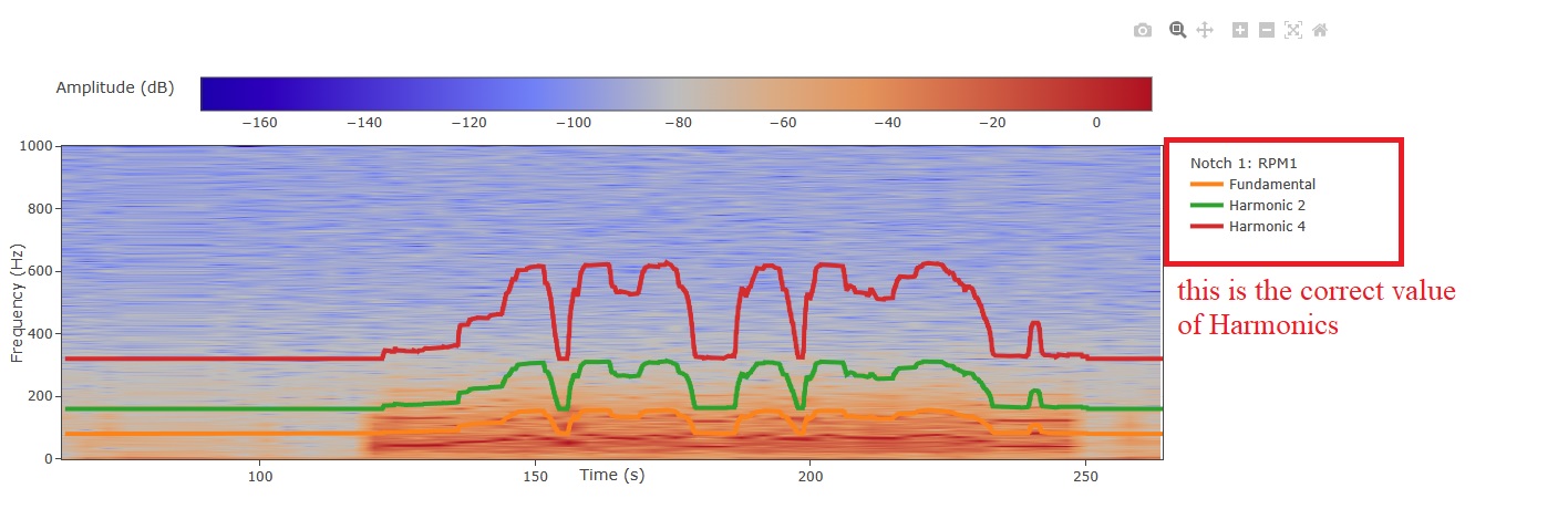
Also keep in mind that when using RPM as the input to HNOTCH, the notch frequency will scale up with the RPM, so I was still thinking my points stand because the notch is not where the noise is, and there’s almost no noise where the notch was ending up. The noise frequency found in the logs doesnt seem to be matching what the expected RPM should be - and an actual flight could probably clear all this up.
In my graphs, the notches would scale up in frequency with RPM, so it shouldnt matter if it’s only starting or warming-up RPM. I would say if the notch cant track the RPM at a low value, then how can we expect it to find and track the higher RPM?
EDIT
What I’m getting at, until we have further info, is the HNOTCH should target the noise regardless of the actual RPM, and we do that by INS_HNTCH_REF,0.4 and some other values. The actual RPM should still scale up the notch filter to suit as RPM changes.
Hello, Shawn! I agree that a real-world flight could probably clarify all of this, which was supposed to be in improving the performance of filters. Now this cannot be done, because flights are prohibited due to the migration of rare birds. Let’s be patient and then not a single animal will suffer from our experiments to improve the performance of filters.
What do you say if you apply only the fundamental harmonic? I can see from the graphs that this reduces the phase delay, it will improve the control loop without degrading the filtering result.
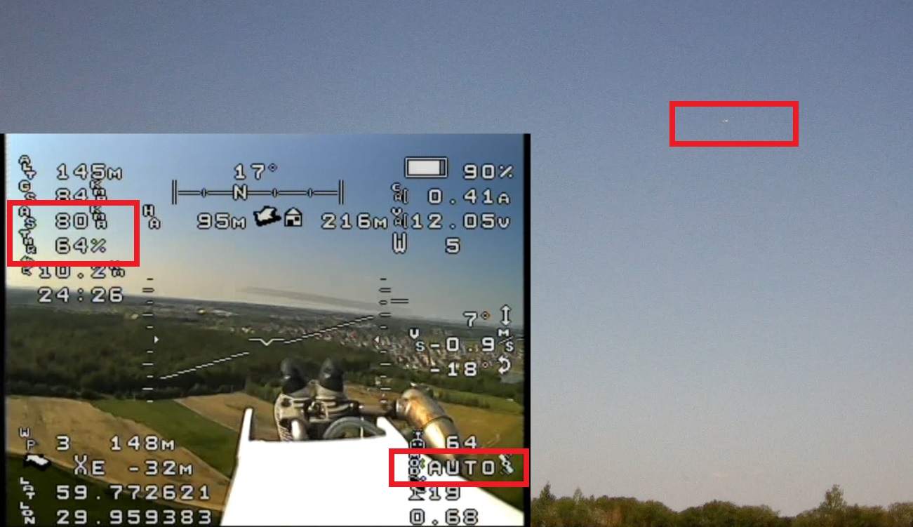
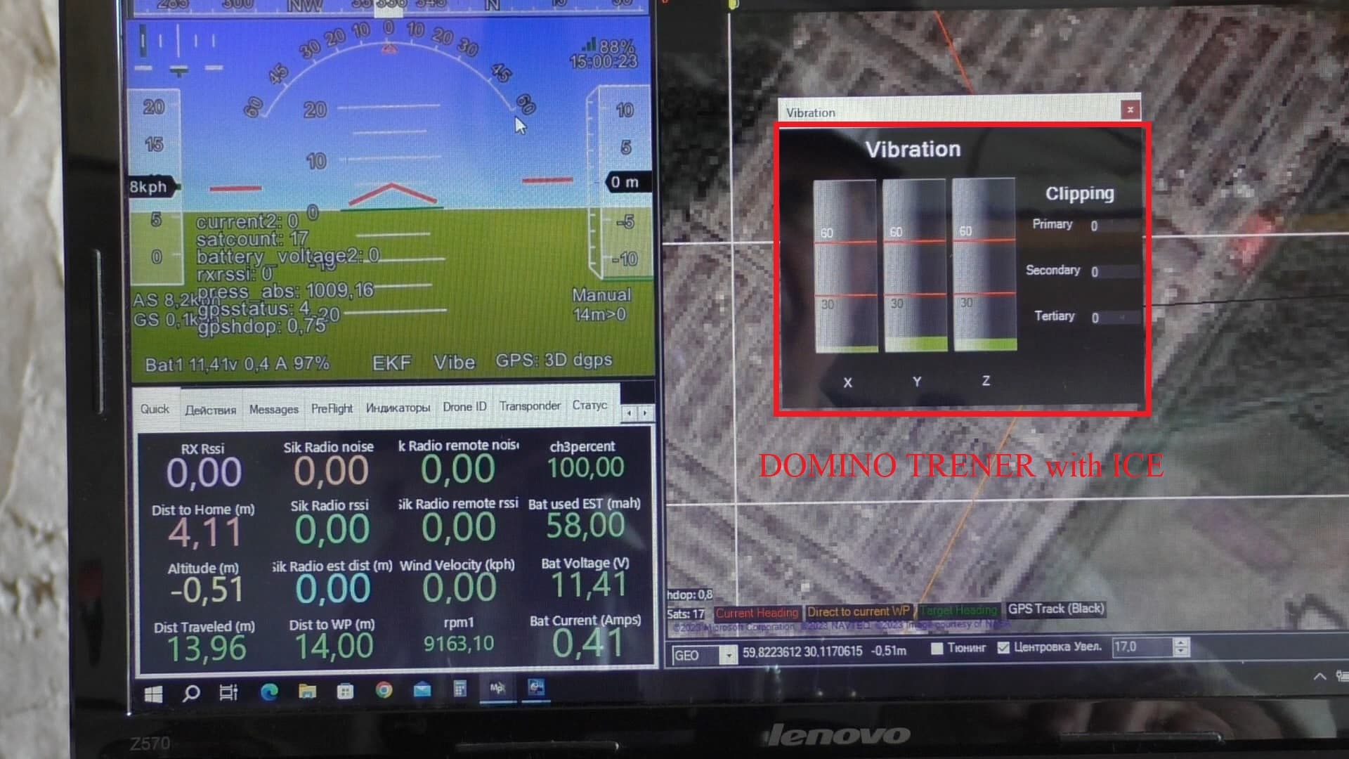
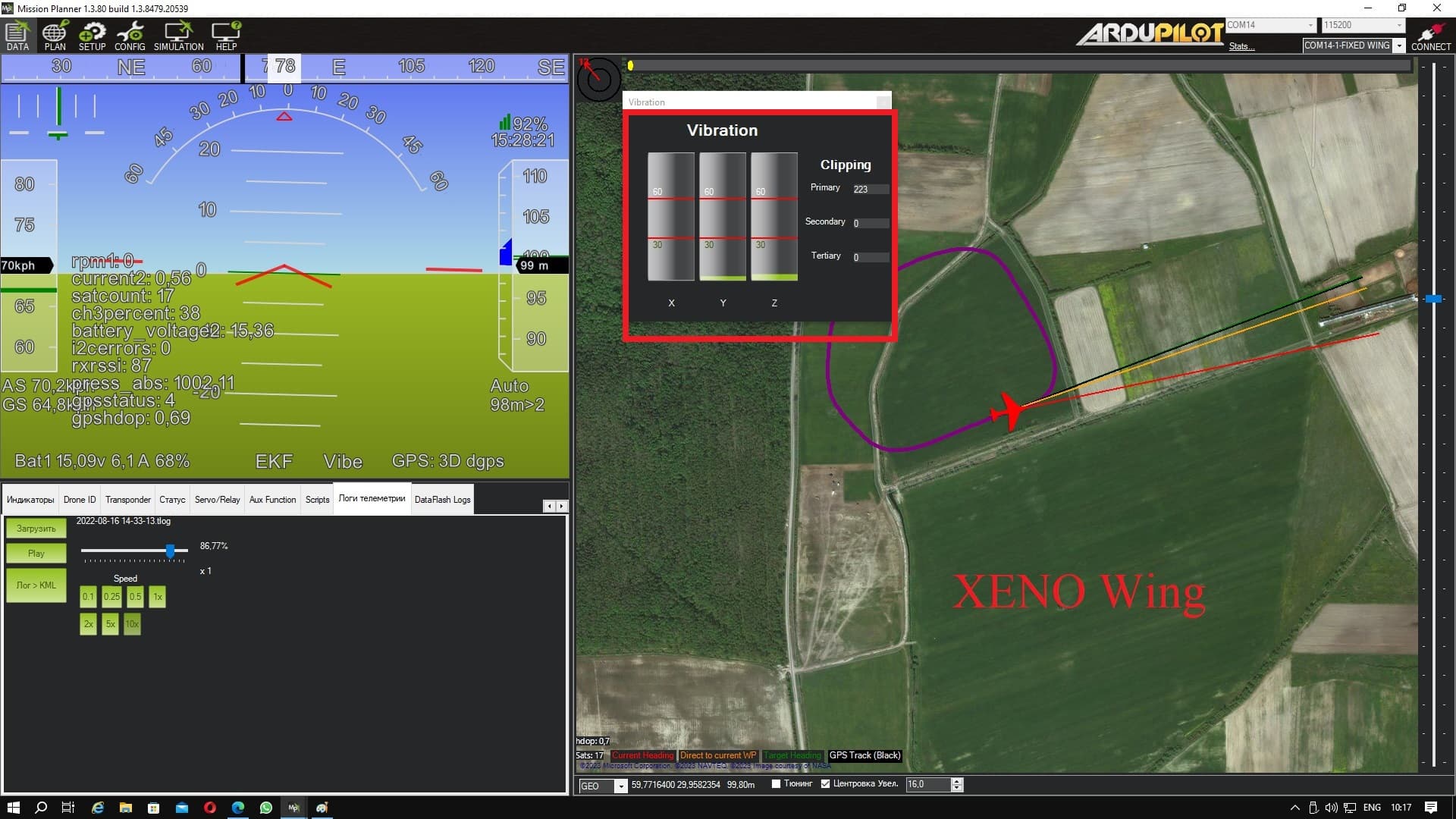
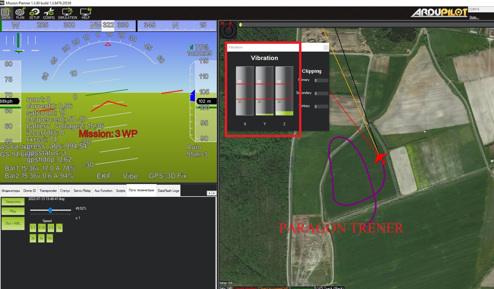
I made a comparison of different aircraft on the VIBE tab. For comparison, I chose two aircraft with an electric motor. XENO is a well-known aircraft from the manufacturer Multiplex. Another aircraft is the same TRAINER, only with an electric engine. As you can see from the VIBE tab, the vibration levels are similar to the result obtained on an aircraft with an internal combustion engine.
This gives confidence that the aircraft with ICE will fly like an electric aircraft. The first flight of the aircraft with ICE was not ideal because no measures were taken to reduce the effects of vibration, so I expect a noticeable improvement in flight performance for automatic mode
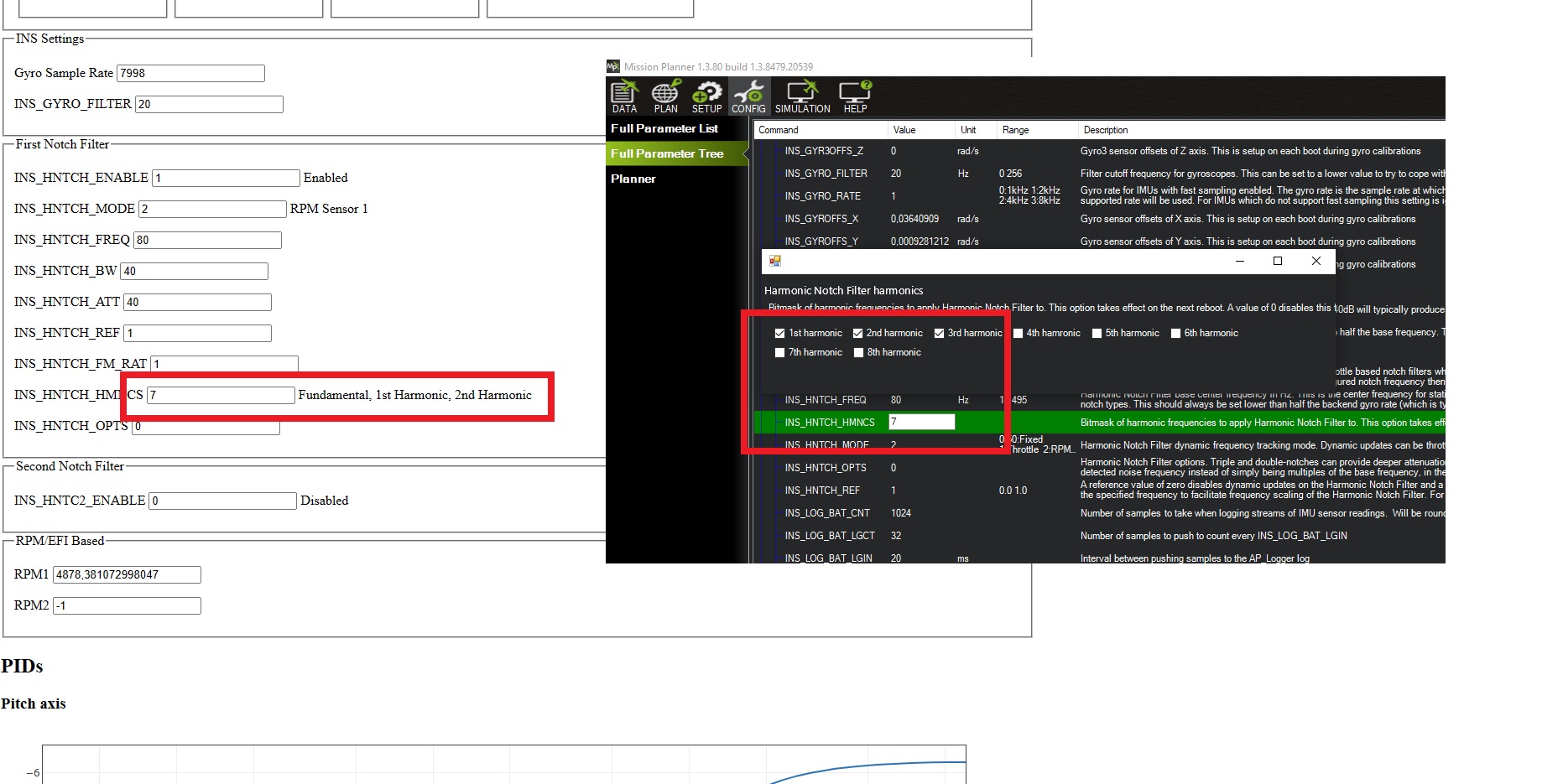
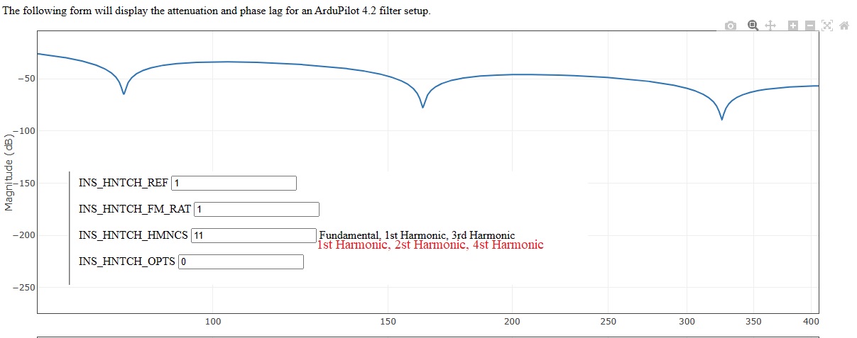
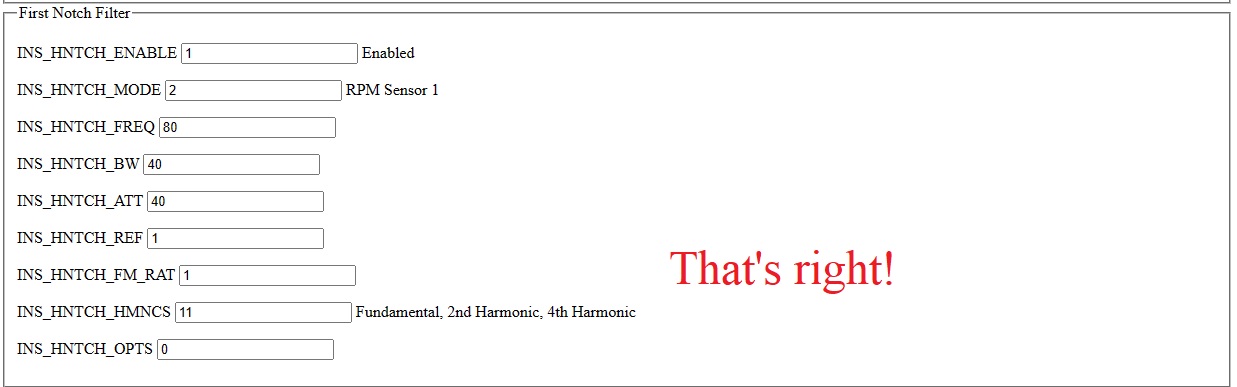
Yes the HMNCS bitmask text is a bit misleading - the text on the left half of you pic is more correct than the text when selecting the bitmask in MissionPlanner.
It should be " Fundamental, 1st Harmonic, 2nd Harmonic…" because that is the result produced by the bit selections.
Yeah happy to wait until the ICE Plane can be tested properly. I’m curious about all this discussion.
EDIT:
My description
Is clearly wrong judging by the discussion below, I wasnt thinking well enough at the time:)
and I defer to Dave and Pete. As Pete says, the filters work as expected based on the bitmask, regardless of how we label things.
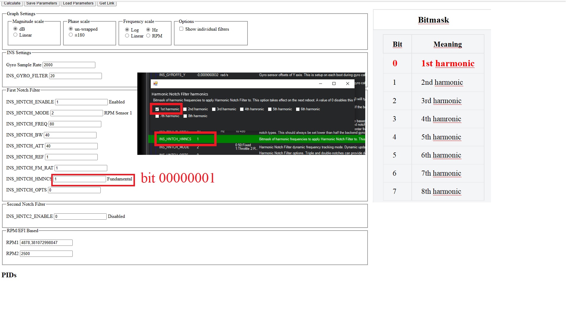
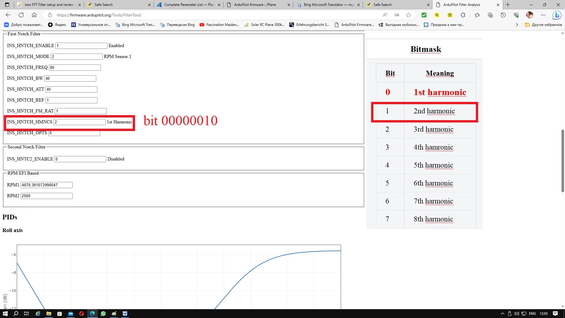
Fundamental it means 1st Harmonic , it follows that the parameter INS_HNTCH_HMNCS = 1. Why does the Filter Tool show INS_HNTCH_HMNCS=2 for 1st Harmonic? In the Parametr List MP, the value INS_HNTCH_HMNCS = 2 corresponds to the 2nd harmonic.
I’m very worried about this. Is there any objectivity in assessing the quality of Filter Tool filtering due to the ambiguous value of the INS_HNTCH_HMNCS parameter?
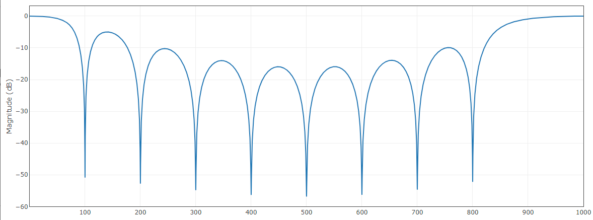
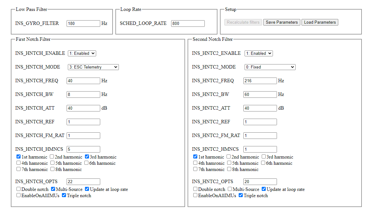
You can look at the plots and see that the harmonics come out in the correct place independently of what the param description says. For example a static notch at 100hz with all 8 harmonics look like this:
This is generated from our param documentation, drop downs and bitmask tick boxes should make it a lot easier to work out what everything does. You can also hover over to get the full param description.
You will also notice a save and load param options in the setup box, this mean you can easy download the config to flash it to the vehicle, or send the log and the config to someone else who can load the log and then the params.
Hello Peter! Thank you for the user-friendly interface, now it has become convenient to do analysis and make the optimal adjustment of filters. I think that the instructions for using your tool should be added to the official ARDUPILOT documentation, for example, in the section Managing Gyro Noise with the Static Notch and Dynamic Harmonic Notch Filters or in Measuring Vibration with IMU Batch Sampler.
I would like to get advice from you on two parameters from my test results, which I indicated earlier in this post.
INS_HNTCH_FREQ= below the hover frequency. In the RPM based dynamic notch, this parameter sets the lower frequency limit of the notch. In tests, I set it to 80 Hz, which corresponded to 2400 RPM for ICE. However, when using the ArduPilot Filter Review Tool, I saw that this frequency should be reduced to 35 Hz, which corresponds to the no-load frequency for ICE.
35 Hz/2 = 17.5 Hz, but I get the best result with a value of INS_HNTCH_BW= 40 Hz.
Do you think it is necessary to observe the proportion in this parameter or trust the results of the optimization of your tool?
It’s a pity that I hurried up with a video review of your tool, yesterday I made a video and posted it on my YouTube channel. However, I hope that your project will improve and later I will make another review, as well as add a video of my flights to it, which will contain the result of filter optimization.