Set the RPM_TYPE to 2, and the RPM_MIN_QUAL to 0.5
The RPM_MIN_QUAL is a 5 element buffer/mode filter that compares timing errors between pulses on the interrupt. With it set to zero it discards all the timing samples.
Set the RPM_TYPE to 2, and the RPM_MIN_QUAL to 0.5
The RPM_MIN_QUAL is a 5 element buffer/mode filter that compares timing errors between pulses on the interrupt. With it set to zero it discards all the timing samples.
Chris, I put the price you gave me.
I’m sorry, but I can not get any price this time.
I did not use the governor.
I connected this same sensor to pixhawk aux5.
I don’t understand what you’re saying?
Set the values I noted and also reset the minimum rpm back to the default of 10. I’m using the same type of sensor on a Pixhack V5, Copter 3.6.0 ChibiOS and it works fine. The RPM value should show -1 with no signal.
Perhaps your sensor is faulty, you don’t have the right air gap to the magnet, or you are using a completely different sensor that is not compatible. I don’t know. But there is nothing wrong in the code because I have been testing governor code with it on Copter 3.6 for better than two weeks.
Since the signal is on an interrupt you have to be careful with y-cabling and matching resistances between two connected devices to the same cable. The interrupt senses when the pin goes high and if you have another device that is causing too much pull-down on the circuit it won’t work.
I’m sorry to have been troublesome First, there is no problem with the cord or wiring.
Let’s try again with the other factors in mind.
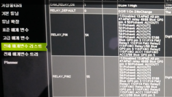
Could you take a screenshot of your latest rpm settings, and the settings for the BRD_PWM_COUNT and the settings for the RELAY_PIN’s?
OK, the reason it doesn’t work is because you got pin 54 and 55 tied up as relay pins. It can’t measure rpm on pin 54 unless you disable that as a relay by setting it to -1.
Thanks Chris
I changed the configuration of the relay pin.
Still no information coming in.
I’m thinking about changing the magnet and magnet sensor this afternoon.
Chris, this could be a rude favor.
Could you tell me the setting of your fc, governor’s wiring or the governor’s settings?
Your coding is perfect I doubt that I made a stupid wiring mistake
I am using a CUAV Pixhack V5, ChibiOS, Copter 3.6. The sensor is a hall effect unit with a single magnet on the autorotation gear from an Aerospire governor. It is hooked up to pin 54 (Aux5).
These are my settings for it:
BRD_PWM_COUNT,4
RELAY_DEFAULT,0
RELAY_PIN,-1
RELAY_PIN2,-1
RELAY_PIN3,-1
RELAY_PIN4,-1
RPM_MAX,10000
RPM_MIN,10
RPM_MIN_QUAL,0.5
RPM_PIN,54
RPM_SCALING,1
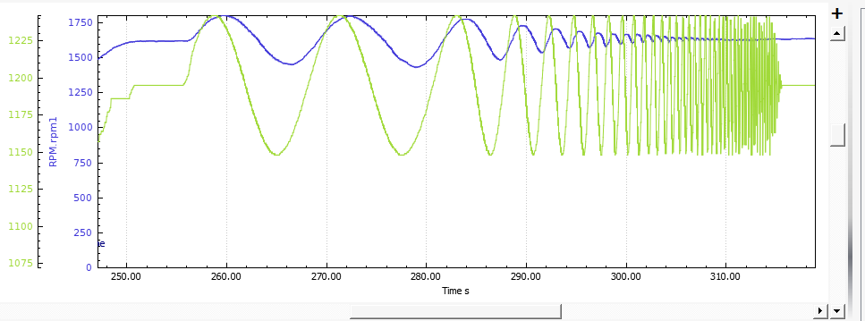
I just got done with a test for designing a governor for ArduPilot using the RPM sensor feature. The test modulated the throttle at a constant engine load to see the delay in the acceleration of mass in the engine and main rotor vs frequency of the throttle change. As you can see, it works perfectly. The blue line is rpm measured by the system, the green line is the throttle output.
Good.
Maybe this is my last question.
If this does not work out, maybe I should think of another way.
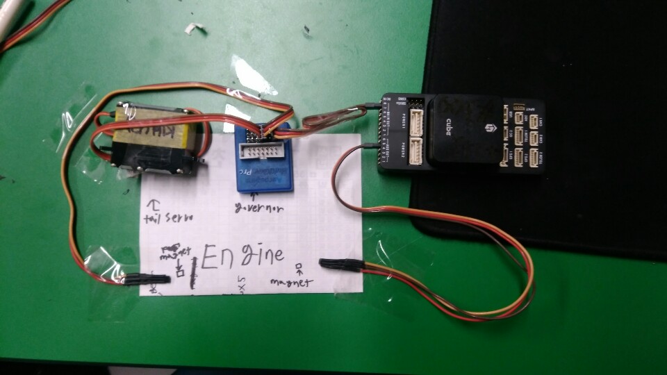
This is my wiring.
I think it’s probably a problem with this basic part like wiring.
First of all,
hall effect unit I do not know exactly what this is …
This is really easy to tell. If RPM is configured correctly, Mission Planner will show rpm1 as -1 when there is no signal (rotor not turning). If it stays at -1 all the time then there is a problem with the sensor. If Mission Planner shows the rpm as 0 when there is no signal, then there is something wrong in the configuration or Pixhawk hardware.
In my case, -1 is displayed correctly.
But I am worried because I can not get the output.
I will change the position of the magnet and sensor attached to the engine tomorrow.
If not, I will buy another sensor.
If the -1 is displayed, then it’s enabled. It’s just not getting a signal from the sensor if you get no rpm reading. You can test it by putting a jumper on from any of the servo output pins to the rpm pin. You must have an active output like the rudder or cyclic servos. It should show 3,000 rpm (50Hz) if it’s working. If it shows that, then you got a sensor problem.
Hi Chris sorry to jump OT. Is the governor code in the ardu repo yet ?
No, it is only engineering test code at this point yet. I’m testing various designs of droop controllers. Too many questions yet as to the design. Do we do a single-speed, do we do idleups, do we do an infinitely variable speed where the pilot can set the desired governor speed with a knob? Haven’t decided that.
I’m hoping to have a beta governor in the next month or so after I do more tests.
Hmmm many valid points. My usage case with a gasser would simply be maintain X headspeed. Stick to a fixed rpm on the rotor head and do not exceed a setpoint of engine rpm.
Would idleups be necessary on an AP equipped rig? At the moment the 5 point curve works well but if I could simply say “hey heli please maintain 1100 RPM headspeed yet don’t over rev past 15000rpm on the engine” it would be a thing of beauty plus one less bit of electronics to mount.
My personal opinion is, no. Idleups come from the 3D aerobatic world where a pilot sets a tame headspeed for takeoff/landing, then flips it into Wild Mode for flight. They are not used in full-size helicopters, running a combustion piston engine at anything other than the range between peak torque and peak hp results in poor fuel economy, and it results in poor performance from the governor. If you operate the engine too close to the knee of the torque curve, it will have no torque rise for the governor to use. If you operate it past the peak hp rpm the engine will experience huge droop on loading that the governor cannot respond to.
When you take into account the characteristics of the engines used in UAV heli’s, plus the gear ratio, this leaves only about 50 rpm main rotor range from optimum where the helicopter will actually perform decent. They are no different than full-size ones in that respect.
However, other folks consider the idleup feature to be something necessary to have. So my opinion is that it is fairly easy to code, you have to expect less than optimum performance if you use it, experienced pilots will not use it.
This does not preclude having a governor trim on a knob or slider like some full-size governors use, such as on the Rolls-Allison 250 turboshaft in the 206 Jet Ranger. That governor is a mechanical unit and it has a trim on the collective lever that the pilot can nudge to get the RRPM needle in the middle of the green to compensate for density altitude. So that is my current idea, maybe allowing a wider range of set speeds for pilots that want to use it. However, the one in the Jet Ranger only allows setting the headspeed from 394 +/- 5 rpm. A change of only about 1% either way.
Hi Chris
I really appreciate it.
Finally, I succeeded in getting rpm !!
I still do not know exactly what the problem is,
I’ve definitely confirmed RPM information from MP in my eyes.
Thank you very much, Chris.
Glad you got it working!