Hi Chris
I got your answer and I tested it right away.
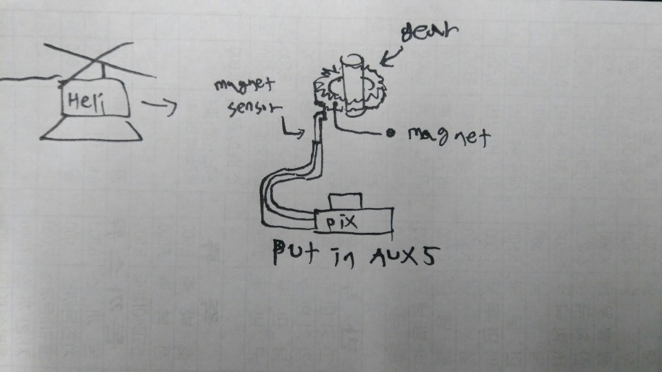
I just moved the magnet sensor from aux2 to aux5.
But the result is not good, I do not get any RPM …
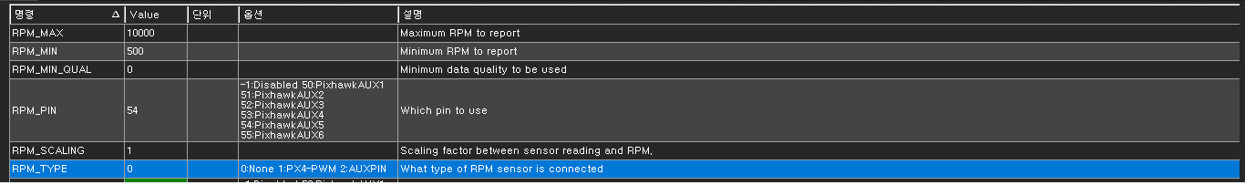
I’ve tried RPM_TYPE 0, 1, 2, but nothing has changed.
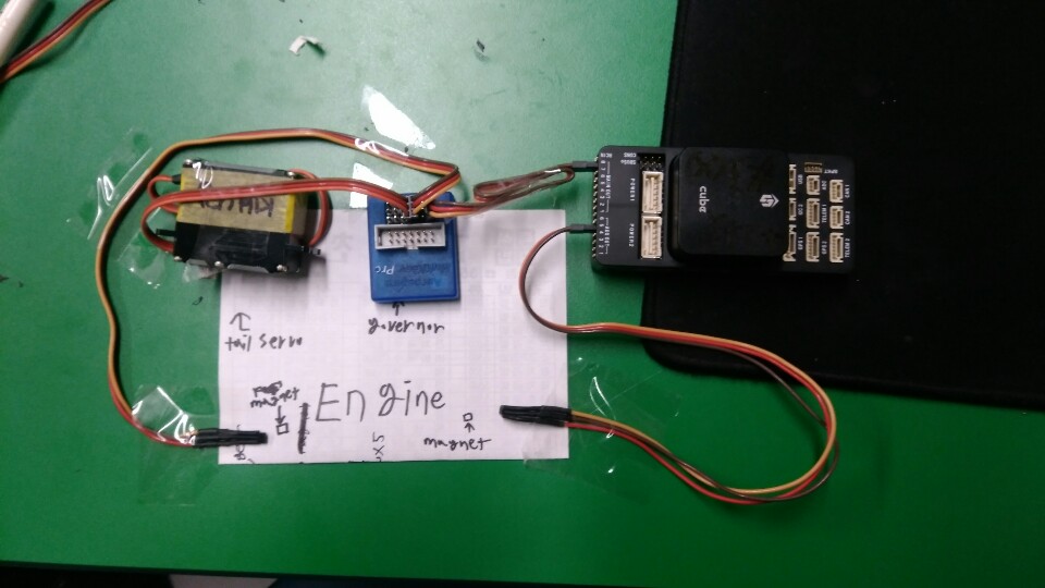
The firmware version is 3.6.0, and now I am connected to the PixHawk this way, is not this the connection?
Set the RPM_TYPE to 2, and the RPM_MIN_QUAL to 0.5
The RPM_MIN_QUAL is a 5 element buffer/mode filter that compares timing errors between pulses on the interrupt. With it set to zero it discards all the timing samples.
Set the values I noted and also reset the minimum rpm back to the default of 10. I’m using the same type of sensor on a Pixhack V5, Copter 3.6.0 ChibiOS and it works fine. The RPM value should show -1 with no signal.
Perhaps your sensor is faulty, you don’t have the right air gap to the magnet, or you are using a completely different sensor that is not compatible. I don’t know. But there is nothing wrong in the code because I have been testing governor code with it on Copter 3.6 for better than two weeks.
Since the signal is on an interrupt you have to be careful with y-cabling and matching resistances between two connected devices to the same cable. The interrupt senses when the pin goes high and if you have another device that is causing too much pull-down on the circuit it won’t work.
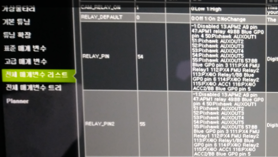
OK, the reason it doesn’t work is because you got pin 54 and 55 tied up as relay pins. It can’t measure rpm on pin 54 unless you disable that as a relay by setting it to -1.
Chris, this could be a rude favor.
Could you tell me the setting of your fc, governor’s wiring or the governor’s settings?
Your coding is perfect I doubt that I made a stupid wiring mistake
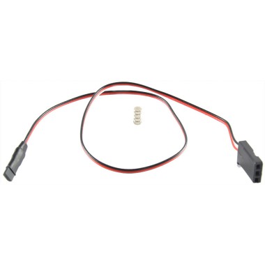
I am using a CUAV Pixhack V5, ChibiOS, Copter 3.6. The sensor is a hall effect unit with a single magnet on the autorotation gear from an Aerospire governor. It is hooked up to pin 54 (Aux5).
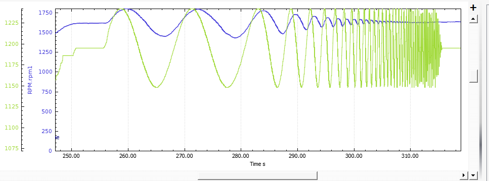
I just got done with a test for designing a governor for ArduPilot using the RPM sensor feature. The test modulated the throttle at a constant engine load to see the delay in the acceleration of mass in the engine and main rotor vs frequency of the throttle change. As you can see, it works perfectly. The blue line is rpm measured by the system, the green line is the throttle output.
This is really easy to tell. If RPM is configured correctly, Mission Planner will show rpm1 as -1 when there is no signal (rotor not turning). If it stays at -1 all the time then there is a problem with the sensor. If Mission Planner shows the rpm as 0 when there is no signal, then there is something wrong in the configuration or Pixhawk hardware.
In my case, -1 is displayed correctly.
But I am worried because I can not get the output.
I will change the position of the magnet and sensor attached to the engine tomorrow.
If not, I will buy another sensor.
If the -1 is displayed, then it’s enabled. It’s just not getting a signal from the sensor if you get no rpm reading. You can test it by putting a jumper on from any of the servo output pins to the rpm pin. You must have an active output like the rudder or cyclic servos. It should show 3,000 rpm (50Hz) if it’s working. If it shows that, then you got a sensor problem.
No, it is only engineering test code at this point yet. I’m testing various designs of droop controllers. Too many questions yet as to the design. Do we do a single-speed, do we do idleups, do we do an infinitely variable speed where the pilot can set the desired governor speed with a knob? Haven’t decided that.
I’m hoping to have a beta governor in the next month or so after I do more tests.