Hi All, The image on the rover page dealing with skid steering shows a two motor rover connected to the pixhawk via a motor controller. This is the configuration I am working on. But the image shows three connectors between the pins of the driver and the pixhawk pins 1 and 3. Now the motors themselves only have two wires red and black. Also the driver only has two pins that control speed and direction of each motor. Can someone help me with pin configuration. I had assumed the third was ground and so connected. My pixhawk smoked and burnt up and I am wondering if this is the reason, I had ground to the top pins. Do I actually need three wires?
1 Like
puedes mandar una foto del controlador?
ese es un controlador para motor a pasos no?
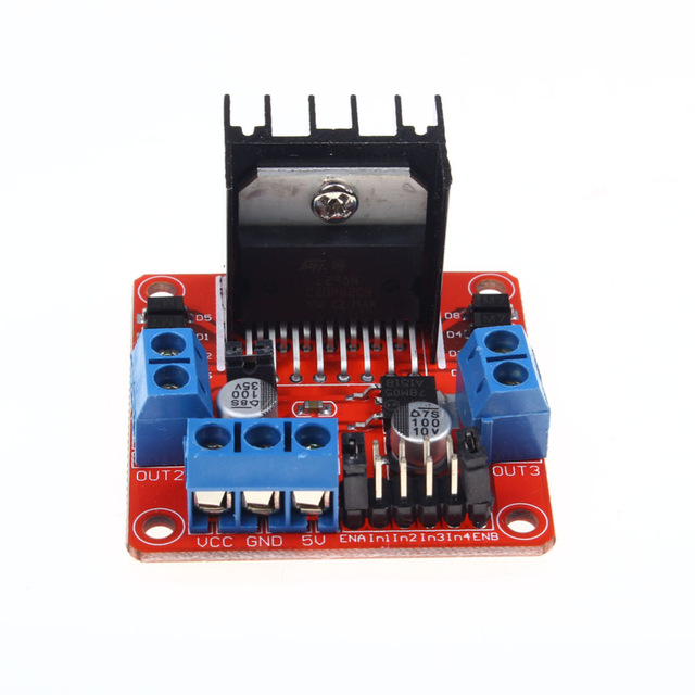
Hi just to clarify This the same controller. I can send picture of it installed if that helps. I used this with a Pi 0w to run my rover using hand controls so I know it works fine and the rover runs ok. I then decided to upgrade to Pixhawk so I can run gps waypoints instead of hand control. It called
Kuman Mini Stepper Motor Drive Controller Board Module L298N Dual H Bridge DC Stepper
si porfavor, si puedes proporcionar una foto de como lo tienes instalado y si puedes mostrar todas tus conecciones probablemente ahi esta la falla, puede que hallas puesto mas de 5v a tu tarjeta pixhawk.
¿que tipo de bateria usas?
¿utilizas algun modulo de poder o como alimentas a tu pixhawk?
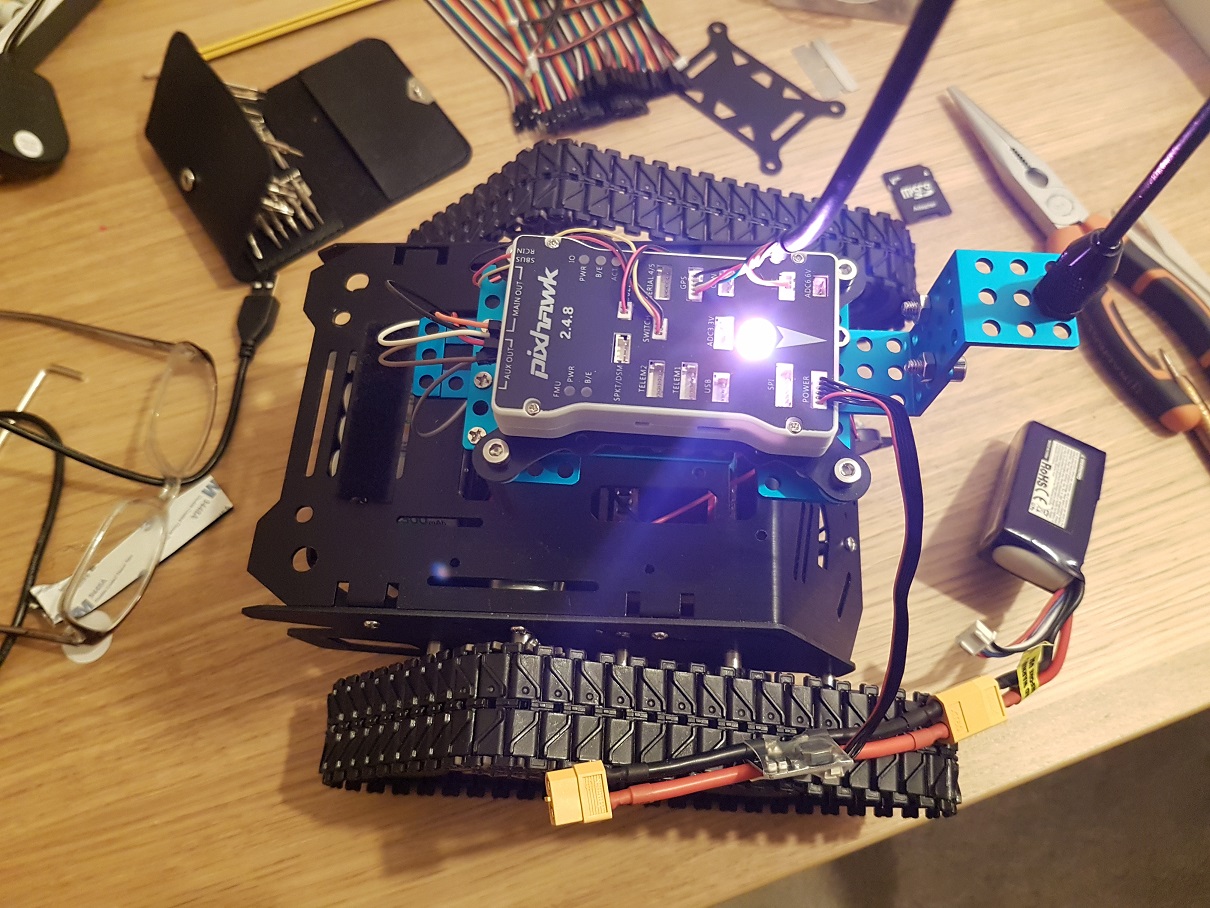
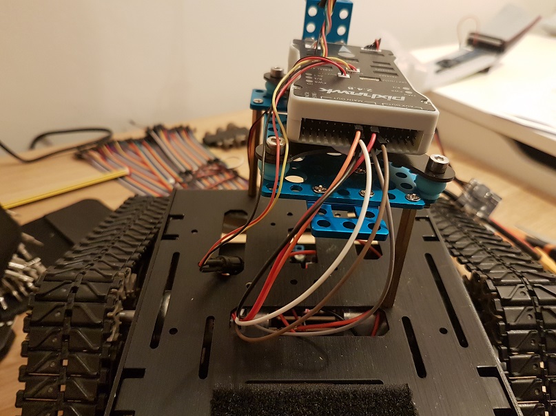
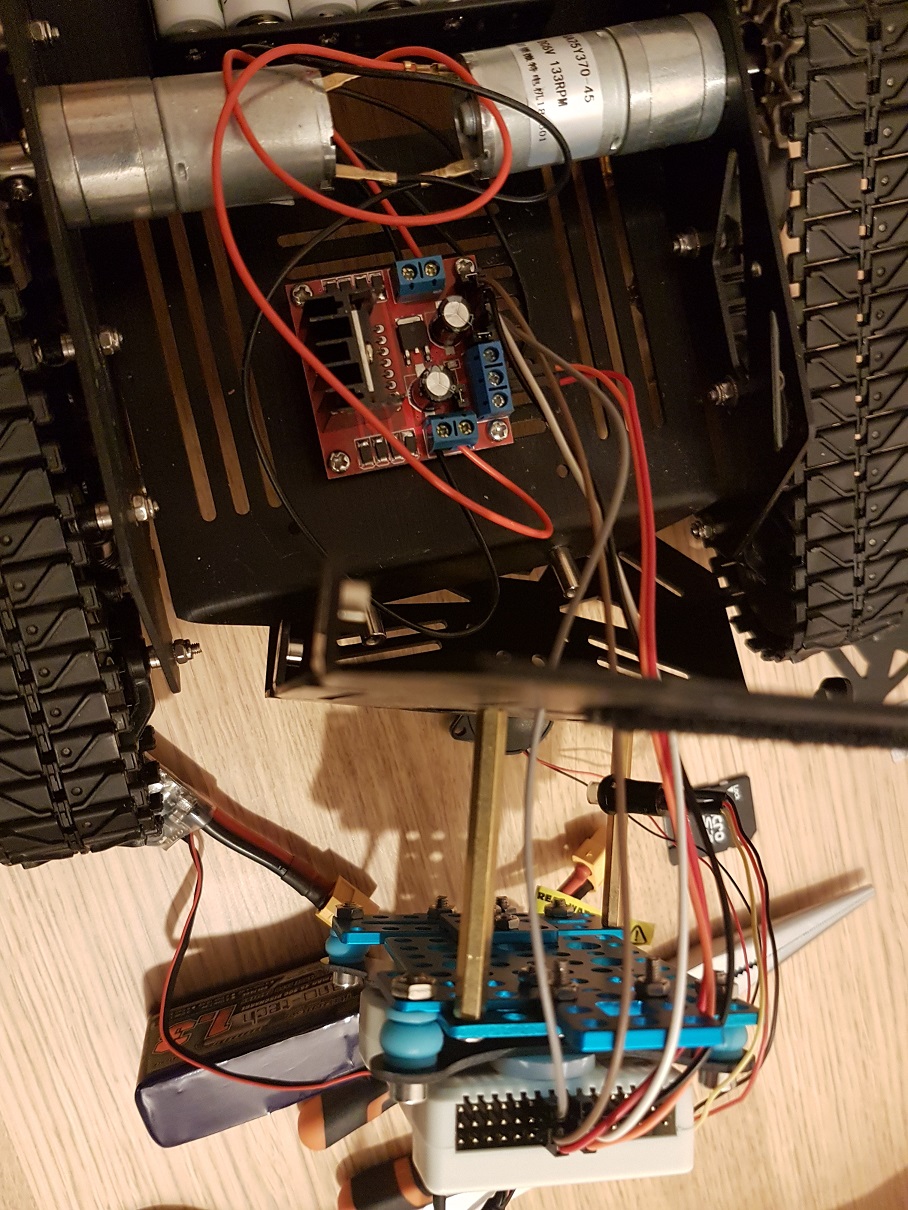
OK so the first picture is of the pixhawk connected to a 3s lipo via an APM power module. Also connected are buzzer, button and GPS. The second picture shows the wires going into pixhawk on 1 and 3. The third picture is inside the rover showing the power module connections. The motors are driven by 8 rechargeable battery. I used a common ground.
por lo que veo tu bateria la tienes en el modulo de poder (o modulo de potencia) pero si lo tienes conectado en la entrada? (in) porque el modulo tambien tiene sentido, en la parte frontal te marca la intrada (in) y la salida (out)
Ok the apm power module has a female and a male connector. As all the Lipo battery have only male I assumed that I connect to the female. Is that not right?
Hi to follow up I examined the APM module and there is a tiny arrow on the Crius chip that points to the male connector so I am assuming that means the male is the output in which case I connected it correctly I think. if it was the other way I would have to get some kind of adaptor as most lipo have a male out.
You can’t power the motors through the Pixhawk. The Pixhawk should just send a PWM signal to your speed controller to tell it how much power to give to the motors
I agree, the pixhawk is connected to the controller pins not to controller power. So these are the same pins I was connected with pi 0w, all they do is trigger the motor to speed and direction.
si, estas en lo correcto, solo si revisa eso, que tu bateria ete conectada en la entrada por que si la tienes en la salida puede que haya sido ese tu problema, que en lugar de pasar 5v a la pixhawk le hayas metido 12v
Ok sorry to clarify the motors are fed from two power output sockets via a 8 AA battery pack completely separate to the pixhawk. The only connection to pixhawk is the pins to manage which way the wheels spin
It’s hard for me to tell in the pictures.
por lo que veo en la foto tiene invertidos los cables de tierra (gnd “-”) y los de corriente (positivo “+”) que conectan a tu pixhawk
In picture 2 what are the wires going into the middle pins on the servo rail? That’s + and should be empty I think. Just trying to help.
La placa L298N tiene un jumper que controla la entrada de tensión.
Con el jumper puesto (como lo tienes en la foto) vale para tensiones hasta 12 V. Entonces metes la tensión de los motores al Vcc y funciona el regulador interno de la placa que alimenta su propia circuitería y proporciona una SALIDA de 5 V. en la marca de 5V, que en este caso debería de estar libre.
Con el jumper quitado. Si la tensión es mayor de 12 V. las pérdidas en el regulador serían muy altas. Entonces se quita el regulador y se alimenta la placa con la tensión de los motores en el VCC y con la tensión de 5V. para alimentar la circuitería de la placa.
Desconozco el resto del esquema, pero con la batería 3s también podrías alimentar los motores.
Un saludo,
Ok I will check this. Is it necessary to use ground at all?