ok I just looked at this. I finally have my dev box up and running again.
So here is the dilemma: ESP32-S3 has three UART controllers, i.e., UART0, UART1, and UART2. Traditionally we reserve uart0 for flashing and debugging and hook it up to a USB controller on the board. So it’s not available unless we do some debugging gymnastics, which let’s try to avoid.
If the possibility exists to need more than 2 serial ports in mav2pt, then we must use SoftwareSerial judiciously to handle the extra ports. In my experience, more than two instances of the SoftwareSerial class don’t play well together. Maybe they do now, but that would need to thoroughly tested. So we have a maximum of 3 ports on the ESPS3 to play with. I need to rationalise port enumeration properly in a logical way depending on options selected, and throw out invalid possibilities. It has grown (like topsy ), and needs cleaning up.
That said, please could you post your full config.h, so I can see your selected i/o use case. Do you want serial FC, serial GCS and serial FrSky port?
Ok. If I am not using it as a Mavlink switch (as well) then I just need 2 UARTS. Is this due to some logic checking in Check Macro Options resulting in Frsky classes not being called? Essentially I am just configuring this in a conventional manner for someone as a gound-based convertor. So my guess is we just need a fed more conditions inserted to make this work. Maybe I should be using the PIO stable for 2.68.3 and applying my pinouts for Heltec Wifikit V3? (Edit: that is not working when I try to compile for a Heltec Wifikit V3 using the PIO stable 2.68.3 where support was added for tthe LillyGo color TFT. It fails to compile as classes related to the TFT display are not invoked – I suspect this is related to the newest target the LillyGo color TFT.
Eric just to be clear – I do not require here three UARTs and Mavlink switch. I am just trying to help people wanting to use a Heltec Wifikit V3 (using the S3) in a Dragonlink setup. No need to go down that rabbit hole. I have custom build for me that work as a Mavlink switch.
Ok Marc. Would you like to give me your pin designations, and I’ll put some macros in to guide the config options to avoid all possible over subscriptions to uarts?
#if (ESP32_Variant == 4) // Heltec Wifi Kit 32 V3 (S3) #define MavStatusLed 35 // Onboard LED #define InvertMavLed false #define BufStatusLed -1 // none #define fc_rxPin 44 // Mavlink serial rx2 #define fc_txPin 43 // Mavlink serial tx2 #define fr_rxPin 26 // FPort rx1 - (NOTE: DON’T use pin 12! boot fails if pulled high) #define fr_txPin 48 // FPort tx1 - Use me in single wire mode
// no GCS serial set up here yet #define sbus_rxPin -1 // not used - don’t care #define sbus_txPin -1 // ?Optional SBUS out pin #define startWiFiPin -1 // Trigger WiFi startup #define resetEepromPin -1 // 5, -1=none use non digital touch pin #if !defined displaySupport // I2C OLED board is built into Heltec WiFi Kit 32 #define displaySupport #endif #define SSD1306_Display // OLED display type #define SCR_ORIENT 1 // 1 Landscape or 0 Portrait
/* Below please choose either Touch pin-pair or Digital pin-pair for display scrolling
* Pin == -1 means the pin-pair is not used
*/ #define Pup -1 // Board Button to scroll the display up #define Pdn -1 // Board Button to scroll the display down #define Tup 45 // 33 Touch pin to scroll the display up #define Tdn 46 // 32 Touch pin to scroll the display down #define SDA 17 // I2C OLED board #define SCL 18 // I2C OLED board #define i2cAddr 0x3C // I2C OLED board #define OLED_RESET 21 // RESET here so no reset lower down
/*
  SPI/CS               05   For optional TF/SD Card Adapter
  SPI/MOSI             23   For optional TF/SD Card Adapter
  SPI/MISO             19   For optional TF/SD Card Adapter
  SPI/SCK              18   For optional TF/SD Card Adapter
*/
Hi been using this for many years ttgo boards
but now i hit an stump i need to build 433mhz 1w system for long range telemetry / mavlink only no control
are the some modules i can use ?
Hi Colin, I have done some work with LoRa and Mavlink, mostly on 2.4GHz using SX1280 boards with LNA +PA. I have some SX1278 boards for 433MHz, and my firmware should work with them, but I have not yet had the time to play with them.
As you know there is a tradeoff between bandwidth and range, so I “compress” essential Mavlink messages into my own short frames and expand again on the other end. While close I just default to hi bandwidth WiFi. Control is included, but I understand you don’t need/want it.
The code is not open source. Maybe it’s best you DM me.
The board + module you propose is good, except it moves data to your microcontroller (like ESP32) via UART, so serial bits. This often too slow.
Better to get, say, E22-400M30S, which moves data via SPI, so parallel bits to CPU and faster.
EDIT: Parallel is not strictly true, but full duplex. Anyway, much faster.
You need one of these transceivers on each end.
You still need firmware in your microcontroller of course. ELRS firmware can work well using CRSF protocol, but there is no open source FW for Mavlink/ Ardupilot as far as I know.
Ok, this is fixed in beta v2.68.10. Only the config.h changed.
I added uart to uart passthrough on esp32S3 for Marc Dornan, so needed gcs pins. Now I just added them to the config.h for older ESP32 variants. I did not have time to choose pins, so designated pin -1 for now.
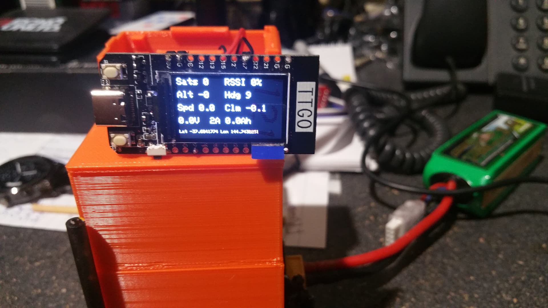
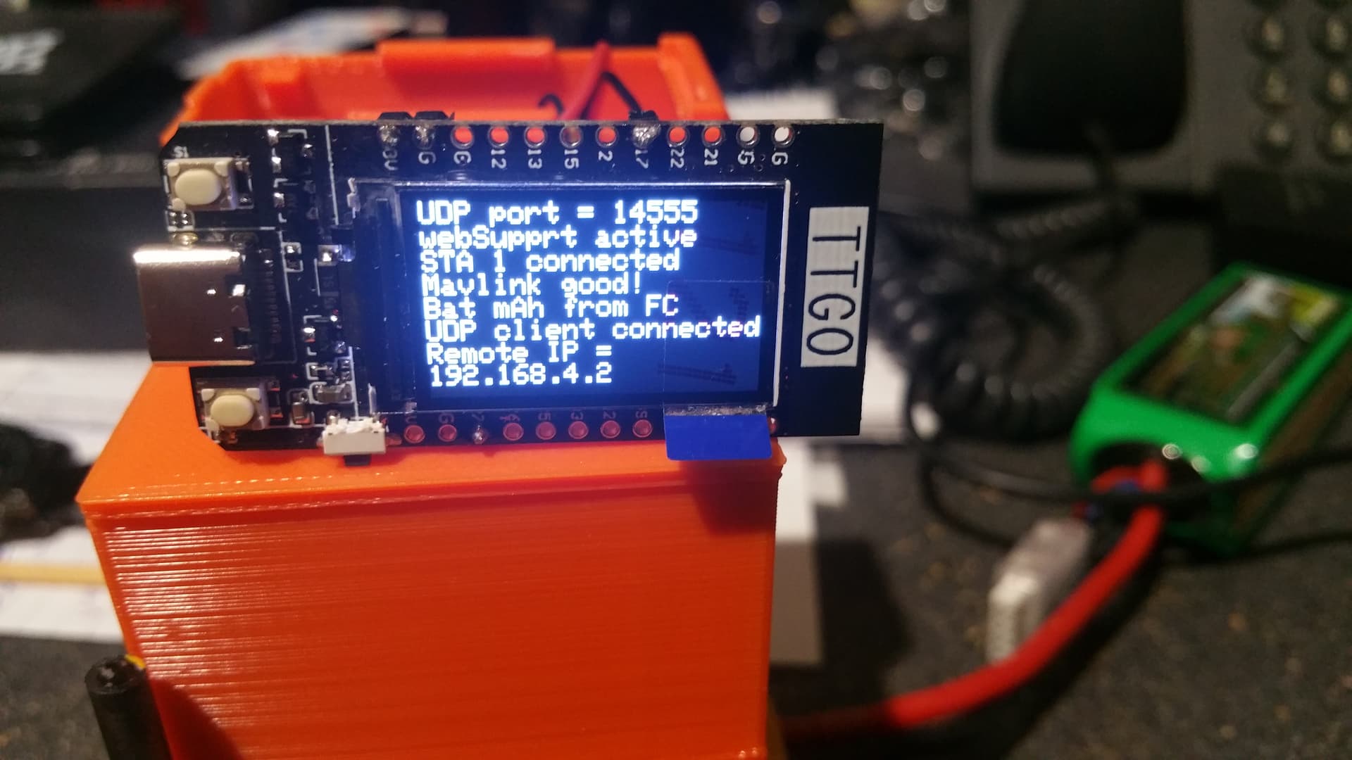
i got the radios to talk to each other
i can get it to work with mission planner over USB out of E77-400MBL-01 the now i will get to work adding your script to an TTG0 T1 so far so good on the display it shows good mavlink and gps but when i try to connect with mission planer over wifi upd port it starts to get the prams and just sits there for ever