Hello everyone, I am trying to get MavToPT working on a nodemcu, the same one that comes in the code, I can compile well and upload to the board, but it keeps restarting all the time. any ideas?
Sure. My problems occurred when using it on an S3 board. I was trying to validate an S3 for a more conventional use (on the back of my Dragonlink TX). The compile errors seemed related to the Frsky Sport code. I will try the 1.68.8 version next week and see how that goes.
“Compiling .pio/build/heltec_wifi_kit_32_V3”, so I assume you selected the heltec board. The S3 has more gpio pins, so for that variant only, I added simultaneous FC and GCS (soft) serial. When the heltec board was selected, there were lose ends. My bad.
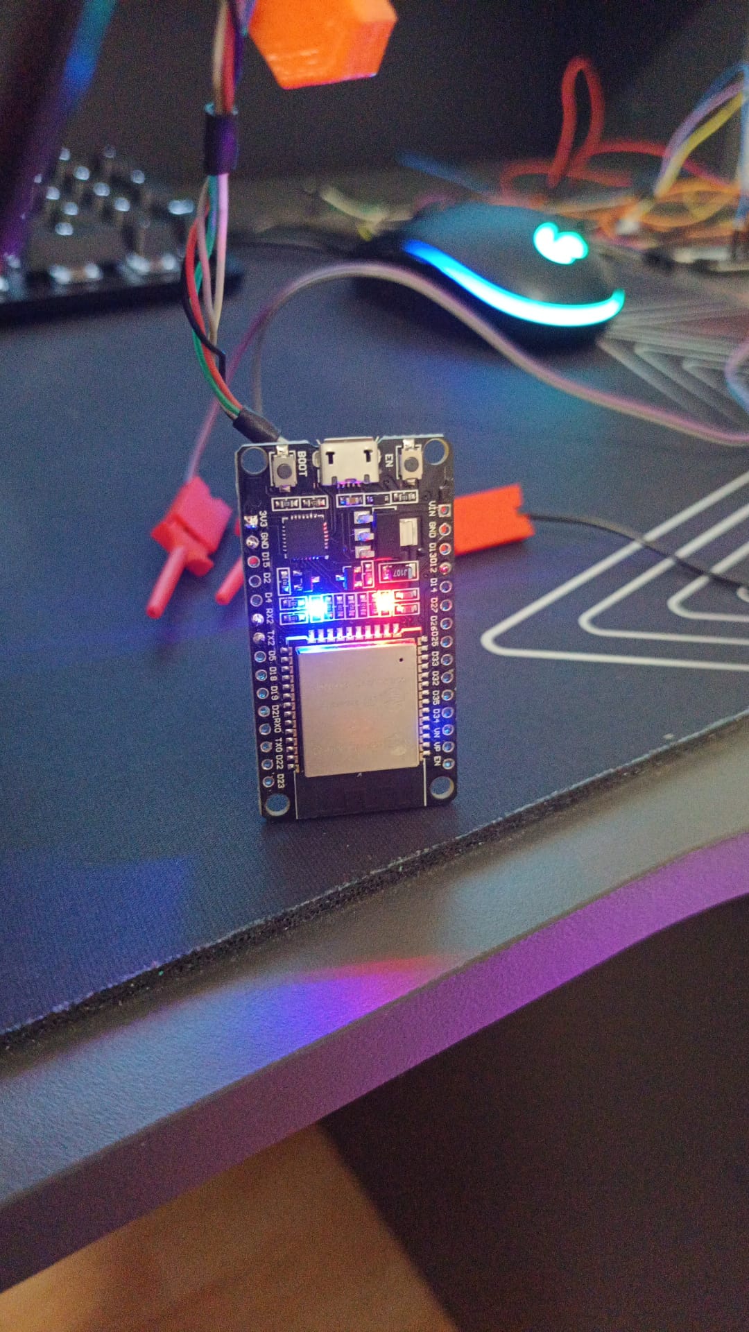
Hi Eric, sorry for the delay, I have changed to an esp32 board, and it seems to work correctly if I connect the telemetry directly to the input serial, for example, from a pixhack. but when I connect to the UEXP of the DL in radiomodem mode, the blue LED blinks. Mavlink is reaching the DL, since I can output it through the integrated BT, but I can’t get the ESP32 with Mav2pt to work, I have checked the baud and everything seems correct, any ideas?
#Update - I realize I was using an older wip version instead of the mav2pt_2.68.06. I just tried the latest and I get exactly the same results. I am only making minor changes to config.h so I am not re-attaching that. It indicates it is connected but no Mavlink is being received.
Eric,
Just an update on my Tracker mavlink bridge – currently it is of the copper wire variant! That S3 dev version you did in August flashes to the board just fine, and it does everything seeming correctly. It gets assigned an IP by my Dragonlink ESP32 (a Heltech v2 board) but it is not working as a Mavlink switch. Tried a few times. I have no issue connecting a GCS via UDP so I know the Mavlink is fine.
Sorry it took so long to get back to this.
The config.h file is here in case you see anything nonsensical.
I was going to test your latest WIP for the Heltech v3. I actually was able to modify the stable release to make this work on PlatformIO and I tested it back in August. I never tested your WIP firmware though – I am looking around for my v3 Heltech to test it now since I am making another repeater setup so its a timely time to test it so we can get these into stable. I will buy another on Amazon to test it if need be.
Hi Marc, all noted. I have a project on the back burner to convert to platformIO, but life keeps intervening.
Ok, so the second ESP32 is reading UDP packets (supposedly), and sending a serial stream.
uint16_t UDP_localPort = 14555; // readPort - (default 14555) remote host (like MP and QGC) expects to send to this port
uint16_t UDP_remotePort = 14550; // sendPort - (default 14550) remote host reads on this port
If DL ESP32 is sending on port 14550, and MP expects to receive on 14550, then GCS works fine.
So ESP32 #2 should also receive on 14550, and send on some other port number of your choosing. Then GCS(2), or tracker, or… must be set to receive on that second port number, right?
I’m just making sure that you remember to “cross over” the port numbers, like we cross over rx/tx lines.
This little app can be quite useful while debugging UDP traffic. Also, you could un-comment appropriate debug macros to check out what’s happening. I don’t have a suitable testbed for mav2PT right now.
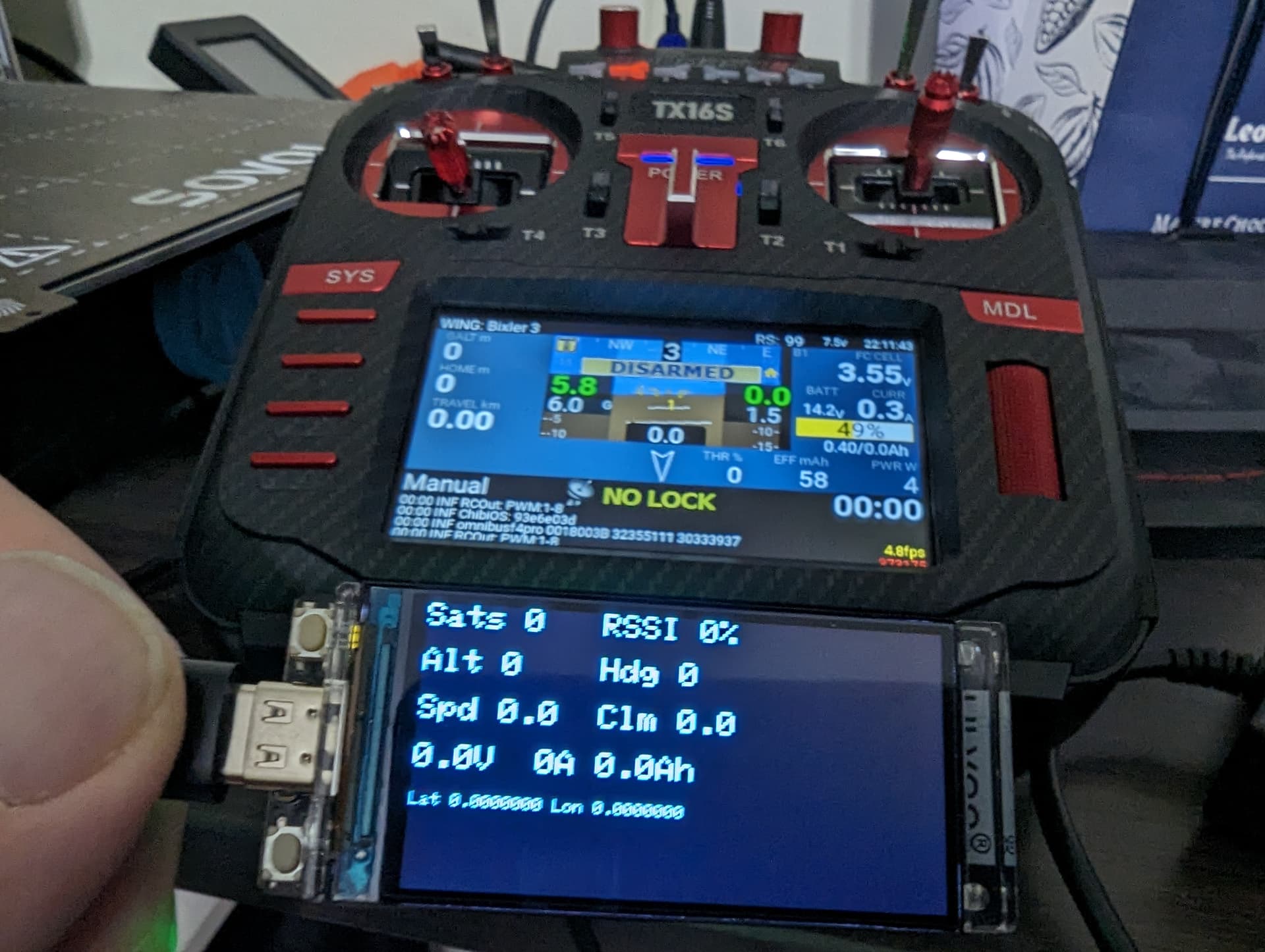
Yes, I get that I think. I have not changed the UDP ports in config.h. My tracker only needs to receive Mavlink packets on a serial rx line and does not transmit so the tx line is not connected. It knows nothing about udp ports. I was expecting the RSSI, voltage and heading readings on the tracker ESP32 to not show zero as this indicates it is not receiving Mavlink packets, right? I should get confirmation on the OLED that I am receiving Mavlink packets?
Gotcha. So if I re-enable Frsky telemetry conversion then I should maybe start to see if those populated. Good to know. I will work on this again next week.
I am trying to recompile with Frsky telemetry support so I can see values in the OLED and confirm that Mavlink packets are being received on the LillyGo S3 being used to feed the tracker. When I un-comment the Frsky telemetry options I get a compile error.
First we get this stopping it:
if(ESP32_Variant == 8)
#if (GCS_Mavlink_IO == 0) #if ((FC_Mavlink_IO == 0) || (FrSky_IO == 1)) #error Not enough UARTS on ESP32S3 #endif #endif
But I have enough UARTS as I am not using a UART to receive Mavlink.
When I comment above out it still fails (seems there are missing declarations in frSky_Ports.h):
In file included from src/main.cpp:137:
include/frSky_Ports.h:2986:14: error: no declaration matches ‘uint32_t FrSkyPort::getBaud(uint8_t, pol_t)’
Am I missing something here? Can’t see why the second error is happening.
Your WIP for Heltech Wifikit 32 V3 (S3) needs these pin assignments to work. I tested it.
#if (ESP32_Variant == 4) // Heltec Wifi Kit 32 V3 (S3) #define MavStatusLed 35 // Onboard LED #define InvertMavLed false #define BufStatusLed -1 // none #define fc_rxPin 44 // Mavlink serial rx2 #define fc_txPin 43 // Mavlink serial tx2 #define fr_rxPin 26 // FPort rx1 - (NOTE: DON’T use pin 12! boot fails if pulled high) #define fr_txPin 48 // FPort tx1 - Use me in single wire mode
// no GCS serial set up here yet #define sbus_rxPin -1 // not used - don’t care #define sbus_txPin -1 // ?Optional SBUS out pin #define startWiFiPin -1 // Trigger WiFi startup #define resetEepromPin -1 // 5, -1=none use non digital touch pin #if !defined displaySupport // I2C OLED board is built into Heltec WiFi Kit 32 #define displaySupport #endif #define SSD1306_Display // OLED display type #define SCR_ORIENT 1 // 1 Landscape or 0 Portrait
/* Below please choose either Touch pin-pair or Digital pin-pair for display scrolling
* Pin == -1 means the pin-pair is not used
*/ #define Pup -1 // Board Button to scroll the display up #define Pdn -1 // Board Button to scroll the display down #define Tup 45 // 33 Touch pin to scroll the display up #define Tdn 46 // 32 Touch pin to scroll the display down #define SDA 17 // I2C OLED board #define SCL 18 // I2C OLED board #define i2cAddr 0x3C // I2C OLED board #define OLED_RESET 21 // RESET here so no reset lower down
/*
  SPI/CS               05   For optional TF/SD Card Adapter
  SPI/MOSI             23   For optional TF/SD Card Adapter
  SPI/MISO             19   For optional TF/SD Card Adapter
  SPI/SCK              18   For optional TF/SD Card Adapter
*/