Ah, ok, thanks for the nice explanation Erwin. Yes, I’m sure we can find a good solution.
A few things first:
-
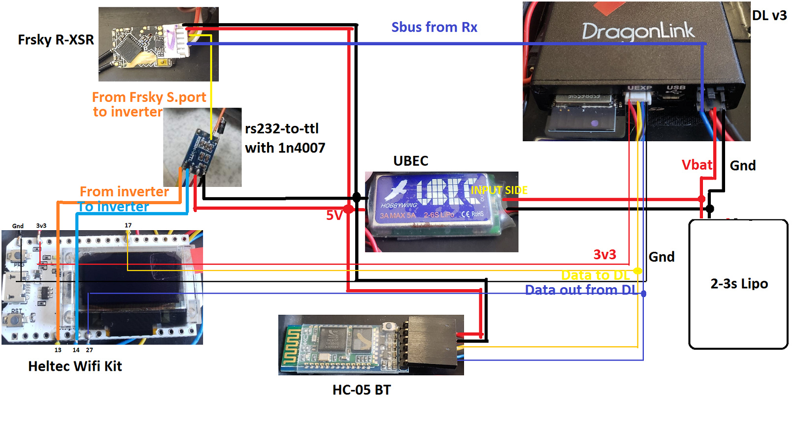
On a serial port, you may share the tx pin (telemetry out) with as many device’s rx pins as you like, as long as you don’t load the pin down. So DL tx pin to HC-05 and Heltec WiFi Kit is not a problem.
-
You may not electrically share rx pins (telemetry in), without taking special steps. So DL rx to HC-05 and Heltec won’t work. Why is this important? On a tracker, maybe not, as it usually does not need to ask the FC for anything special. (My tracker anyway, can’t be sure about the Crossbow mini).
However, if you want the data path from the Flight Controller to go all the way to a ground station like Mission Planner or QGC, those GCSs definitely need to request parameters and other things from the FC, so two-way or half-duplex telemetry is essential in that case.
If your telemetry path branches off to a tracker that simply reads gps data, that particular fork of the data path does not need an uplink path to the FC.
So, let’s try to simplify the architecture. What if we lose the HC-05 and use the Heltec, as it stands, to talk FrSky passthru to the R-XSR as it does now, but in addition using WiFi to a second ESP32, also running Mav2PT. Mav2PT can work as a switch, similar to mavproxy. The second esp32 connects to the Heltec via wifi (could be either udp or tcp, your choice, or BT for that matter) and talks to the tracker rx/tx via serial port.
So the second esp32 would be setup like this:
// How does Mavlink telemetry enter this translator?
//#define FC_Mavlink_IO 0 // Serial Port (default)
//#define FC_Mavlink_IO 1 // BlueTooth Classic - ESP32 only
#define FC_Mavlink_IO 2 // WiFi - ESP32 or ESP8266 only
//#define FC_Mavlink_IO 3 // SD Card / TF - ESP32 only
// How does Mavlink telemetry leave this translator?
// These are optional, and in addition to the S.Port telemetry output
#define GCS_Mavlink_IO 0 // Serial Port - simultaneous uplink and downlink serial not supported. Not enough uarts.
//#define GCS_Mavlink_IO 1 // BlueTooth Classic - ESP32 only
//#define GCS_Mavlink_IO 2 // WiFi - ESP32 or ESP8266 only - auto selects on ESP8266
//#define GCS_Mavlink_IO 3 // WiFi AND Bluetooth simultaneously.
The serial pins on the second wifi board, if it is a heltec, would be 17 and 27.
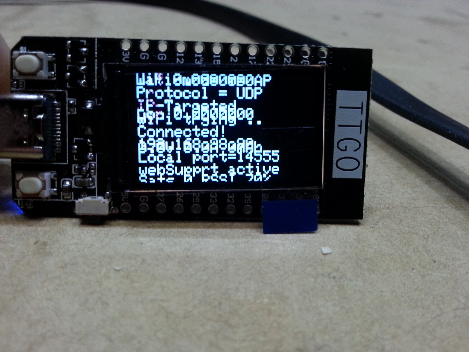
Remember, on mav2pt the #define options only establish the settings the first time the firmware runs. From then on, you must use the web interface. On the web interface, the settings for the second esp32 would look like this:
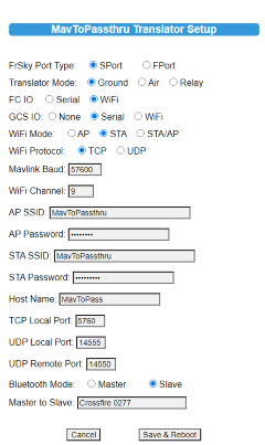
I suggest that the Heltec WiFi be in AP mode and the second esp32 in STA mode, and be sure to use identical protocols (say TCP), identical ports (say 5760) identical SSIDs (hotspot name) and identical passwords. If you use UDP, be sure that remote and local port numbers match. These little details can screw you and waste a lot of time if you are not very careful.
If you want/need to tag on a ground station, simply connect that to the Heltec WiFi, no problem.
To be clear, it does not really matter which end of the wifi connection is the access point, and which the station. There are all sorts of permutations which will work if you understand the issues. For example, you could connect both to a local LAN, but let’s leave that discussion for another day.
One last thing: Wifi (and Bluetooth) share the 2.4GHz consumer band with regular rc radios (and microwave ovens  ) . They usually manage to get along, but be aware.
Hope this helps. I’ve got a lot going on, so might not be able to get back here as often as I would like.