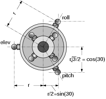
It has become evident that servo displacement between the three swashplate servos has to be consistent throughout the full range of servo movement to keep from introducing coupling between pitch, roll, and collective. If the servo arm movement stays within +/- 30-40 deg of rotation from trim (which assumes the arm is perpendicular to the linkage at trim), then error between a linear throw and the actual throw is +/-4%. For servo arm throw up to 60deg then the error increases to a max of 14%. Since the swashplate orientation relies on all three servos, even errors of 4% can introduce coupling.
Unlike other servos, the swashplate servo min and max is fixed to 1000 and 2000 and is not able to be changed by the user. Well they can change it but it will be set back to 1000 and 2000. Since the min and max is fixed, I can make an assumption that 1000 and 2000 pwm is an arm angle of +/- 60 deg. Thus assuming a 1 inch arm radius, the max linear displacement of the arm is sin(60 deg) = 0.866. So I equate the full linear displacement to 0.866. So a request of 0.1 from the code would equate to 0.0866 actual arm throw linear displacement, if the arm was 1 inch long. Now the arm angle is back calculated to give that displacement. In this case it would be arcsin(0.0866)=4.97 deg.
I will put some graphs in illustrating the difference in the servo movement. I just wanted to socialize this idea as I move forward. It would definitely be a user selectable feature because there is certain criteria in the setup to get this to work properly.
I think your method will probably work and prevent servo binding for four-servo swashplates (when eventually supported).
For 135/140 swashplates (not currently supported in Copter) that have a 1:1 ratio for servo movement for any control input in any direction, this issue is non-existent if the mechanical part of the system is set up correctly. It is why these heads were designed for 3D.
For 120 swashplates where the servos move in a 2:1 ratio for elevator input, it becomes an issue at full collective travel. Even at zero collective with a 120 swashplate, with everything set up perfectly, I can measure .008" movement in collective with a dial indicator on a combination elevator/aileron input. Which only makes the helicopter fly sloppy compared to commercial FBL units that are able to tune this interaction out.
There’s also servo placement relative to swash.
There’s horizontal displacement at servo ball causing slight tilt on the link. This is probably negligible but gets worse with shorter links.
Symmetrical placement eg.SAB Goblin eliminates this inequality
Credit: Avantrc, Raptortechnique.com
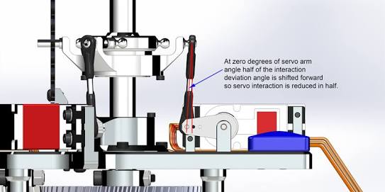
Various manufacturers have done different things to mitigate the geometry issues. On the Thunder Tiger heli they use these rate multiplying linkages to place the linkage to the swash at ideal geometry. And adjust the geometry of the swashplate to make it 1:1 ratio for the servos. And it actually works. There is zero interaction on any control input in any direction. And it is very noticeable in how the heli flies - supremely accurate on control inputs.
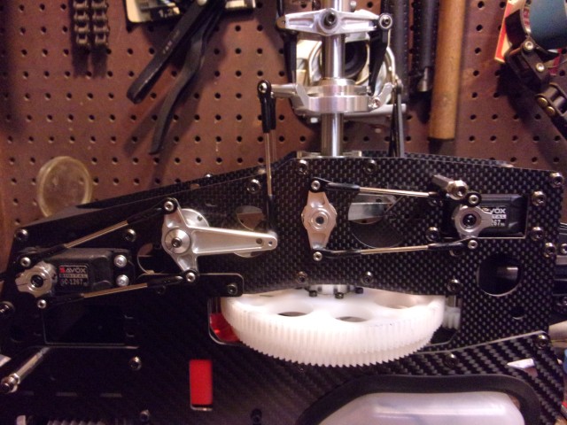
By contrast, this is the layout for a typical 120 degree swashplate. Not quite perfect and requires some compensation mixes to get “pure” inputs.
Chris,
I can see how the H3-140 helps with keeping the servo rates equivalent but I fail to see how coupling due to the servo arm circular motion is eliminated with the H3-140. Now that I see the thunder tiger implementation, I agree that would reduce or nearly eliminate the coupling. However a H3-140 swashplate alone would still suffer from coupling due to circular arm motion. Certainly a similar set up for an H3-120 as the TT would help reduce but like you point out, there would still be some coupling due to servo rates.
Looking at the TT set up, that brings up a good point about my planned implementation. My current implementation assumes the servo arm is directly connected to the swashplate linkage or the arm length for the bell crank and servo are the same. This technique would have to be adjustable and is dependent on the bellcrank or servo arm connected to the swashplate linkage.
It is kind of a unique setup for the TT. There is 3mm lock rods that goes thru the arms and holes in the frame to center everything and level the swash. Then the servos are started up and centered at 1500, H_COL_MID is set at 1500 and you lock the servo horns to the shaft cores.
Instead of the swash moving up to increase pitch to hover, it goes down to increase pitch. This seems to keep the linkages at more of an ideal angle to the arms. And any control input deflects one arm one way, and the other the other way, the same amount. So it is sort of self-compensating for the arm arc travel.
If it does have any interaction, I can’t measure it with a dial indicator over the full collective range I have set of -2.5 to +10.8 degrees. Measuring the collective change on either roll or pitch input the needle on the indicator, with the plunger on the swash ball, stays at whatever it is measuring for collective travel, and does not vary even with the width of the needle, which is <.0005" (five ten thousandths of an inch).
My H_COL_MID is at 1500, H_COL_MAX at 1660 to get 10.8 degrees. So it’s fairly quick on the mechanical rate.
I just had some questions regarding how ArduPilot linearizes the swashplate movement.
The following is some code from the AP_MotorsHeli_Swash.cpp file
 // @Param: LIN_SVO
    // @DisplayName: Linearize Swashplate Servo Mechanical Throw
    // @Description: This linearizes the swashplate servo's mechanical output to account for nonlinear output due to arm rotation.  This requires a specific setup procedure to work properly.  The servo arm must be centered on the mechanical throw at the servo trim position and the servo trim position kept as close to 1500 as possible. Leveling the swashplate can only be done through the pitch links.  See the ardupilot wiki for more details on setup.
Another part of the code is the following:
// get_servo_out - calculates servo output
float AP_MotorsHeli_Swash::get_servo_out(int8_t ch_num, float pitch, float roll, float collective) const
{
    // Collective control direction. Swash moves up for negative collective pitch, down for positive collective pitch
    if (_collective_direction == COLLECTIVE_DIRECTION_REVERSED){
        collective = 1 - collective;
    }

    float servo = ((_rollFactor[ch_num] * roll) + (_pitchFactor[ch_num] * pitch))*0.45f + _collectiveFactor[ch_num] * collective;
    if (_swash_type == SWASHPLATE_TYPE_H1 && (ch_num == CH_1 || ch_num == CH_2)) {
        servo += 0.5f;
    }

    // rescale from -1..1, so we can use the pwm calc that includes trim
    servo = 2.0f * servo - 1.0f;

    if (_make_servo_linear == 1) {
        servo = get_linear_servo_output(servo);
    }

    return servo;
}

// set_linear_servo_out - sets swashplate servo output to be linear
float AP_MotorsHeli_Swash::get_linear_servo_output(float input) const
{

    input = constrain_float(input, -1.0f, 1.0f);

    //servo output is calculated by normalizing input to 50 deg arm rotation as full input for a linear throw
    return safe_asin(0.766044f * input) * 1.145916;

}
From what I understand, the code is doing the following. This may be wrong so please correct me:
- Calculating the servo output pwm value needed between -1 to 1 depending on the type of swashplate to achieve a certain pitch/roll/collective.
- Take arm radius to be 1cm. 1*sin(50 degrees) = 0.766044cm. This is mapped to a pwm signal of 1. So the linear displacement (cm) vs PWM signal graph would follow the graph of y = 0.766044x.
- The code takes that servo pwm output from step 1 between -1 to 1, and then finds the linear displacement you would get. So for example, a PWM signal of 0.5 would give 0.383022 cm.
- Then it uses safe_arcsin to calculate the angle needed by the servo to get that linear displacement.
- It multiplies that angle by 1.145916. (WHY ??)
I am struggling to understand how using this method you are able to achieve linear servo movement and was hoping if anyone could explain.
Also, if this option is used, what are the requirements for the mechanical setup of the servos in order for this to work?
And does servo trim position mean the neutral position?
And why must it be at 1500, and what does this number represent?
@Suhayl_Patel First here is a post that describes the setup for the linear servo feature. Be sure to read the first and second post as I tried to provide a little more clarification on the setup of the linear servo.
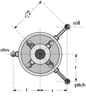
First this implementation assumes that 1000 pwm equates to servo arm movement of 50 degrees in one direction and 2000 pwm equates to 50 degrees in the opposite direction. and of course 1500 pwm equates to the arm centered. Assuming a unit radius arm, at 50 deg arm rotation, the linear movement of the end of the arm is 0.766 (see below)
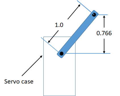
Now 0.766 is the maximum linear movement of the arm in one direction for the max or min pwm. This is equivalent to the max input request of the control system which is -1 to 1. So an input request of 1 should be 0.766 in one direction and -1 should be 0.766 in the other direction. Therefore the angle of the arm to achieve the linear output from 0 to 0.766 is calculated by arcsin(0.766* x) where x is the input request from the controller.
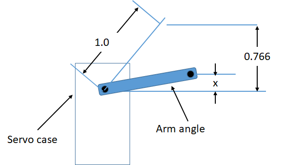
The output of the equation above is the arm angle to achieve the linear output requested by the controller. This now has to be converted to a pwm output for the servo which equates to an arm angle. the output to the servo in the code is -1 to 1 which equates to 1000 pwm and 2000 pwm. So the arm angle in radians is divided by the equivalent of 50 deg in radians which is 0.8726. But for coding purposes, multiplication is faster so I multiply by the inverse which is 1.145916. this normalizes the output to the servo.
Hopefully this makes sense.
@bnsgeyer After reading your reply and the post that you linked, I understand how the linear servo feature works.
In summary, the servo arm should be in its mid position, with the servo linkage to the swashplate being perpendicular to the arm, when the swashplate is in the hover collective position.
Me and my team at university are designing a custom heli that will run ArduPilot, and will have a payload that it will be able to drop. We are using a T-rex 550E Pro DFC rotor head and swashplate.
We wanted to create an optimisation software in Excel that uses the genetic solver function in Excel to calculate the required servo horn length, servo linkage length and servo position to give the best mechanical setup, whilst the linear servo mechanical throw option is on. What performance measure do you think we should try to optimise the setup for, so that we get the best mechanical setup integrated with the linear servo function?
And since we are dropping payload, the hover collective would change. Have you got any advice on how we could accommodate for this?
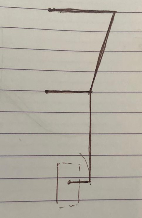
Also would it be possible to use the linear servo function in the following format, so that when switched to manual mode, you are able to do 3D flight?
If you are planning to be able to do 3D flight then I would set the mid servo position for 0 deg collective. The suggestion I made above was for a UAV heli where collective blade pitch range is -2 deg to 10 deg.
Not much you can do in manual modes like acro and stabilize. The modes that use altitude hold feature will automatically adjust collective to stay at the desired height once the payload is dropped.
I think you are pretty locked into a specific setup unless you are making a new frame. Also the throw required to pitch the blades x deg is fixed by the control horn. If you don’t intend to do acrobatics then set the collective range for a UAV heli. If I had the ability to adjust the things you state above. You want to use the full throw of the servos to achieve the collective and cyclic extremes. Thus you get the most resolution ( more PWM per deg of blade pitch) or put another way least blade pitch per PWM.
float servo = ((_rollFactor[ch_num] * roll) + (_pitchFactor[ch_num] * pitch))*0.45f + _collectiveFactor[ch_num] * collective;
When linearisation is on, does the above code mean that 45% of the max linear displacement is allocated to pitch/roll and 55% of the max linear displacement of the servo arm being allocated to collective?
Why is 45% used, if that is the case?
@bnsgeyer @ChrisOlson Sorry for bothering again. I would really appreciate the help on this question.
I don’t think you can look at it that way. These calculations are not designed to equate to the full throw of the servo. The collective is scaled according to H_COL_MIN and H_COL_MAX. The cyclic is added to that. I don’t know how the original developer came up with .45. For most sport helicopters the collective range is small. A collective range of -2 deg to 10 deg results in a PWM range of about 200. So for most UAV helis, they rarely use full throw of the servo to achieve the max extents of collective and cyclic. The servo that would come closest to doing that would be servo 3 for the standard H3-120 servo since it needs the most servo movement to achieve full pitch cyclic throw. Hopefully this answers your questions.