78Hz 1st mode. The 2nd mode is the arms flexing laterally at 88Hz and the 3rd is similar at 108Hz. 1st mode attached. There isn’t a lot of data around to judge good or bad here but those 3 modes are close coupled so a potential problem trying to isolate them even with a compliant FC mount. But that’s what I would do in any case. It would be interesting to compare to CF materials but I have found this difficult to do with proper material properties.
So really just a fun exercise and a break from real work
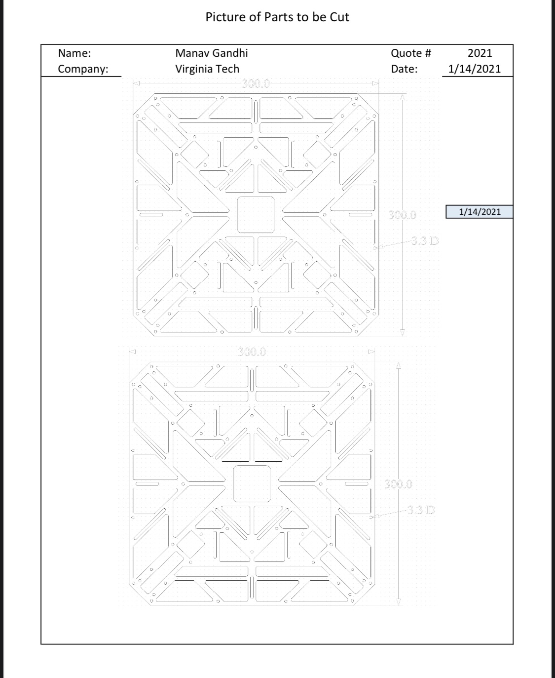
Note: This is with the bottom plate floating. You have a big box below the plate but I’m not sure how it’s attached. The assy model shows it floating in space. It could offer some rigidity depending on how it’s mounted. The dummy motors are equivalent mass to the motors+props. The GPS mounts (assume plastic) are there because they probably add some rigidity
cool, awesome work dave
the 3 frequencies so close to each other might be a issue. Maybe i’ll do a real world test with CF… but first i have to order some plates…
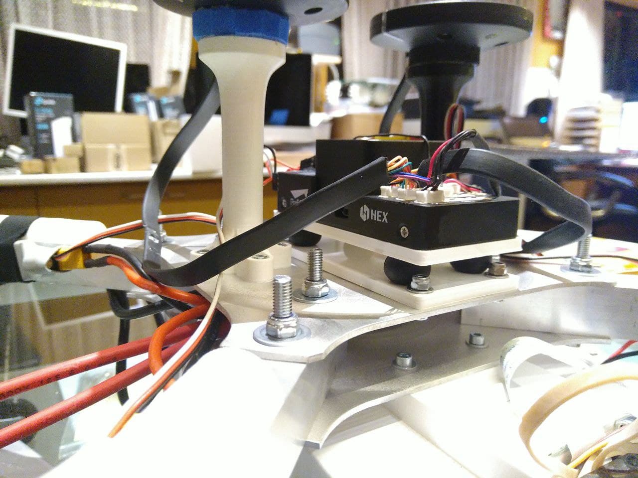
the box below is where the Battery is usually in… it is bolted with 6 M3 Bolts. if you look at the top plate closely you’ll notice 6 6mm holes, these are to reach the bolts on the plate below…
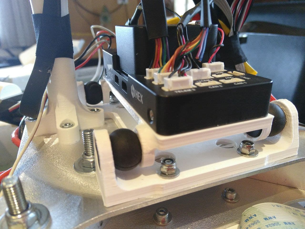
i just 3d printed a very simple vibration damper. i know. a lot of people would burn me now at the stake because the dampeners do not point to the IMU but for a try it should be fine… i’ll test it tomorrow if the weather allows it.
yes, kinda anoying… i just took some balls i have left from a tarrot frame, used for the DSLR Camera gimbal…
do you think it is worth a try with CF center plates? i believe not…
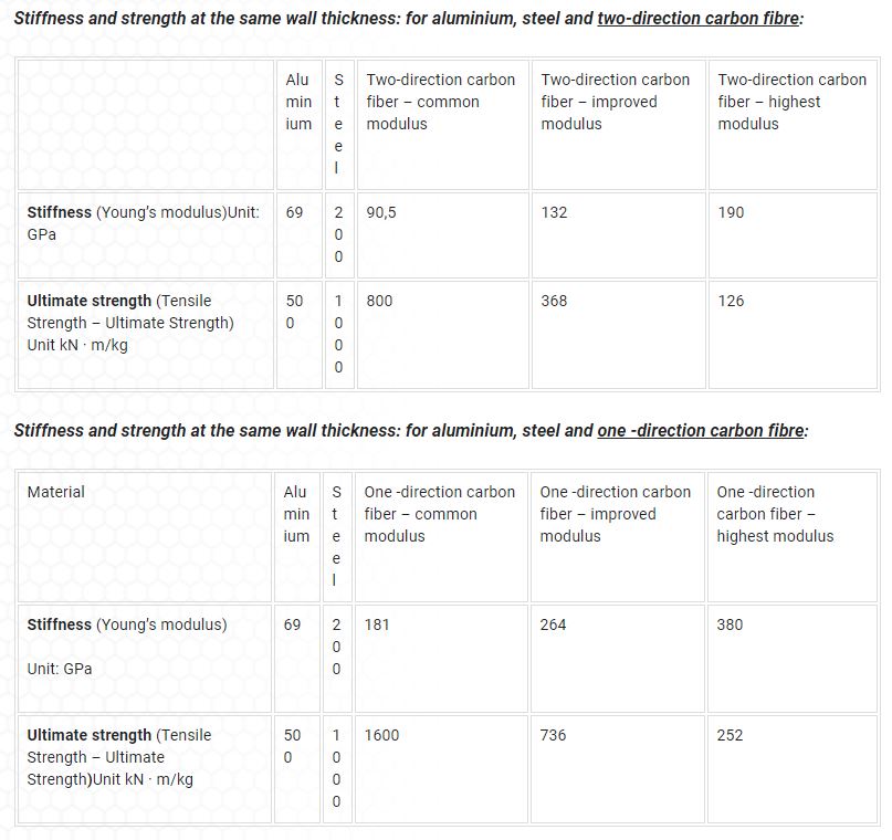
At equivalent thickness it would have higher stiffness. At equivalent weight it would have much higher stiffness.
I would never site a source like this “on the job” and risk being accused of “Google Knowing” but this is just multirotor stuff As the saying goes aluminum is as heavy as a rock!
Note: There is a poster on the forum that uses very thin wall square steel tubing he get’s at the local home improvement store. I believe it’s standard use if for towel racks or something like that. Not that I’m suggesting the use of steel just a contrast.
Well, i think i’ll ask our engineer to do some simulation with different strength of the center plates… I think (without any knowledge ;-)) that just replacing the center plates and keeping the arms in alluminium might not be the solution…
Sometimes i prefer the try and error way than calculating everything to its end… But i have to see where i can get some carbon plates nearby…
I would agree with that. I bet if I run the analysis again and fix constrain the top and bottom plates the 1st mode would increase of course but perhaps not by as much as expected. The aluminum arms will still flap like birds with that Motor/prop mass.
Trial and error… Well, I probably wouldn’t have my job very long by taking that approach. But for this stuff, sure.
Maybe i’ll do some more tests with other vibration dampers and the orange cube… Should arrive next week…
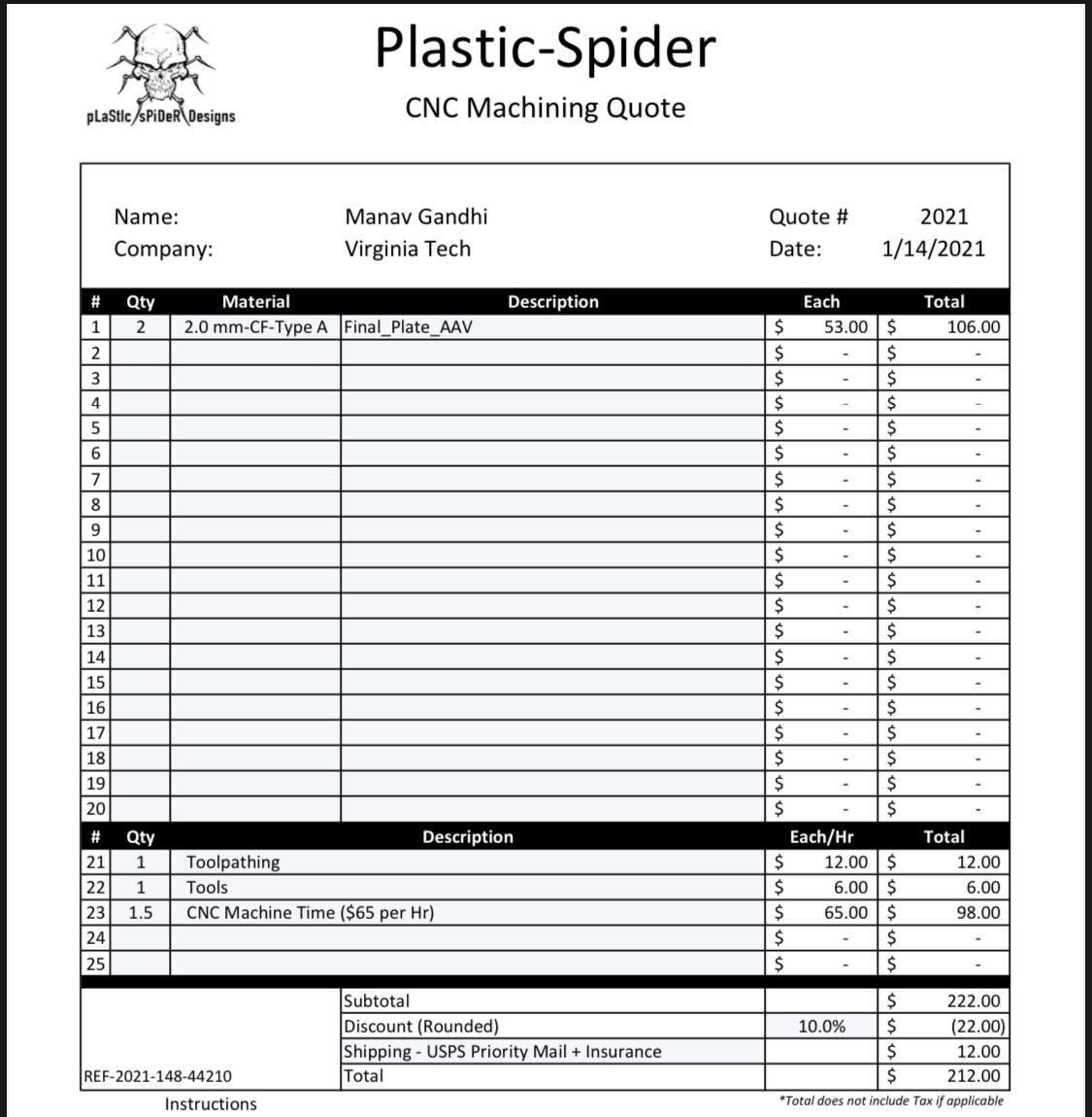
I just found a local dealer for the carbon plates but for a “trial and error” throwing $100 - plus the work for cnc milling them - away might be expensive
Anyway… We’ll se what the future brings…
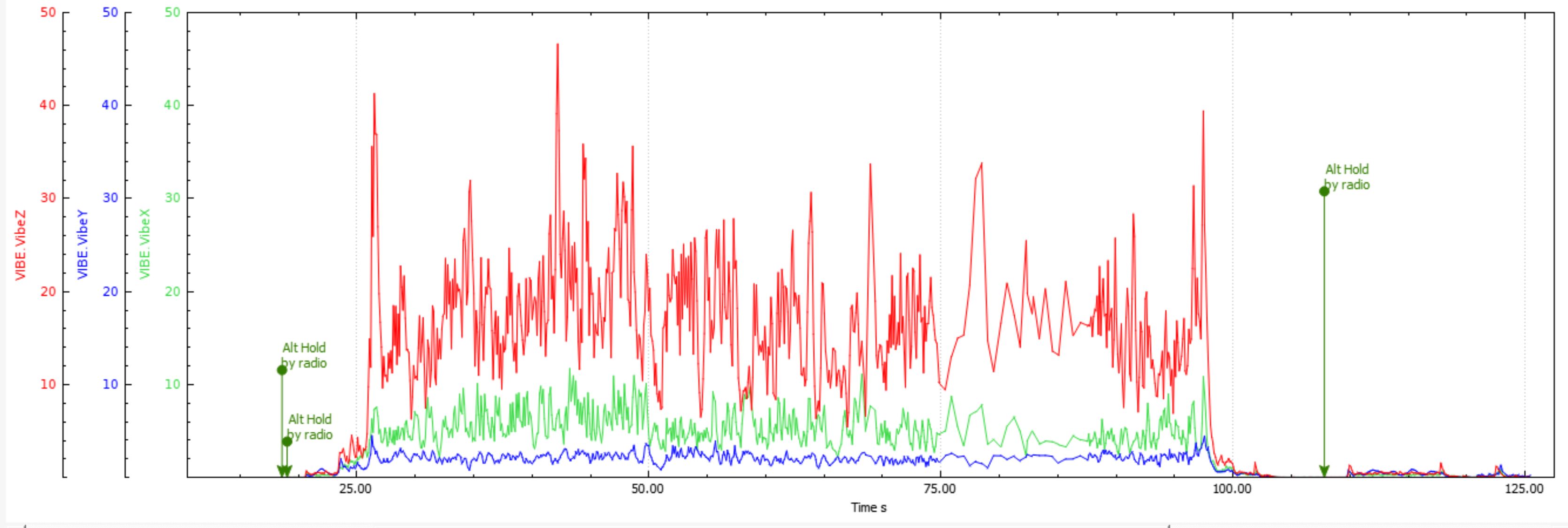
Do you have a explanation why the vibration in hover is close to 0 and then rises that much when increasing speed?
I get my CF plates cut from here. Quick delivery time (5-7 business days) and pretty inexpensive considering that they purchase the material, CNC, finish, and deliver.
thank you for the advice, i’ll take a closer look tomorrow… i am currently experimenting with different vibration damping setups (there is still hope deep inside me ) i’ll post the results later this week