ok guys i did everything like advised by you and would like to say thankyou first
it completed the first longrange flight today (15km at 10m/s) first with the small, then with the big battery
the vibration increased only a little when using the big battery and stayed well below 30 now (mean was 21)
i will do another test tomorrow at higher speed to compare with the failed flight before.
We did some Speedtest Flights today. i made a mission, Do Set speed, then 1km flight, turnaround and come back. then increase the speed and do it again… we did 8, 10, 11, 12 ,13 and 14 meters per second. (Check the log called Speedtest8t14ms.bin)
The Z-axis is getting high when it comes to speed like 13…14 m/s… lower than with the old tuning but i am still not very comfortable…
i guess all i can do now is mount the FC on vibration dampers? we would like to reach about 18m/s cruise speed
Would there be anyway to increase the thickness of those aluminum plates? Usually high vibrations is a byproduct of a frame that is not stiff enough. I have an 18" propeller quadcopter flying at 20 m/s and vibrations in the Z-axis average are well below the limit.
I agree with Manav. Aluminum is not the greatest material for multirotor frames. But short of that put the FC on a ball mount plate. That has worked well for many craft with flexi frames. Dump out the “it must be hard mounted” cool-aid
yes, i can either stack 2 of those plates and bolt them together or go to a metal shop and get thicker plates… but the frame feels pretty stiff, you cannot bend anything by hand…
i will see if i can enforce the frame, if not i will mount it on ball mounts…
btw. i have been reading that the ball mounts should lead to the center of the IMU like this thing here does: https://www.thingiverse.com/thing:3794194
hovewer i do not feel comfortable to put the FC on a fragile 3D printed part. so do you think i can mount it on a regular ball plate?
Stacking two of the plates is a good start to see if it will make any difference. Not being able to bend something by hand usually means the airframe is strong - but for vibrations you are looking at stiffness. The two are slightly different metrics - although they are related to one another.
By stacking two plates you will also be increasing the mass of the center module - which should help with vibration damping as well.
As per putting it on a regular ball plate - I can’t say for sure what your results are going to be. If you already I have one in-house I would def give it a shot in just normal hover to see what it looks like.
The 3D printed mounts are strong enough for the job. The FC shouldn’t experience force that is strong enough to break 3D printed parts. Just print in higher infill if you are worried.
btw i just ordered the cube orange with the ADS-B carrier board for safety reasons. do you guys know if it has better internal vibration dampening than the black? maybe it is worth to give it a try first?
a few seconds later, the model was in a FEM Analysis to see what moves under stress and vibration…
the result was nothing. the frame seems to be stiff enough, we even apllied 10 times the forces that apply during real flight.
but something else may point me in the right direction:
the square shaped arms might end with high turbulence from the propwash. so the idea is to 3D print a wing shaped cover to guide the air around the arm. Might be worth a try
If you have an assy model of the frame and arms with equivalent motor mass ask him to run a natural frequency analysis. It’s what I would do. In fact if you have a .stp file model you wanted to share I could give it a try.
Ok, so you have a naked Cube on “soft” frame, you drop the nose down 20 degrees and haul freight at 50km/h (31 mph) and then you complain about vibrations? I’d be more concerned about WIND BUFFETING.
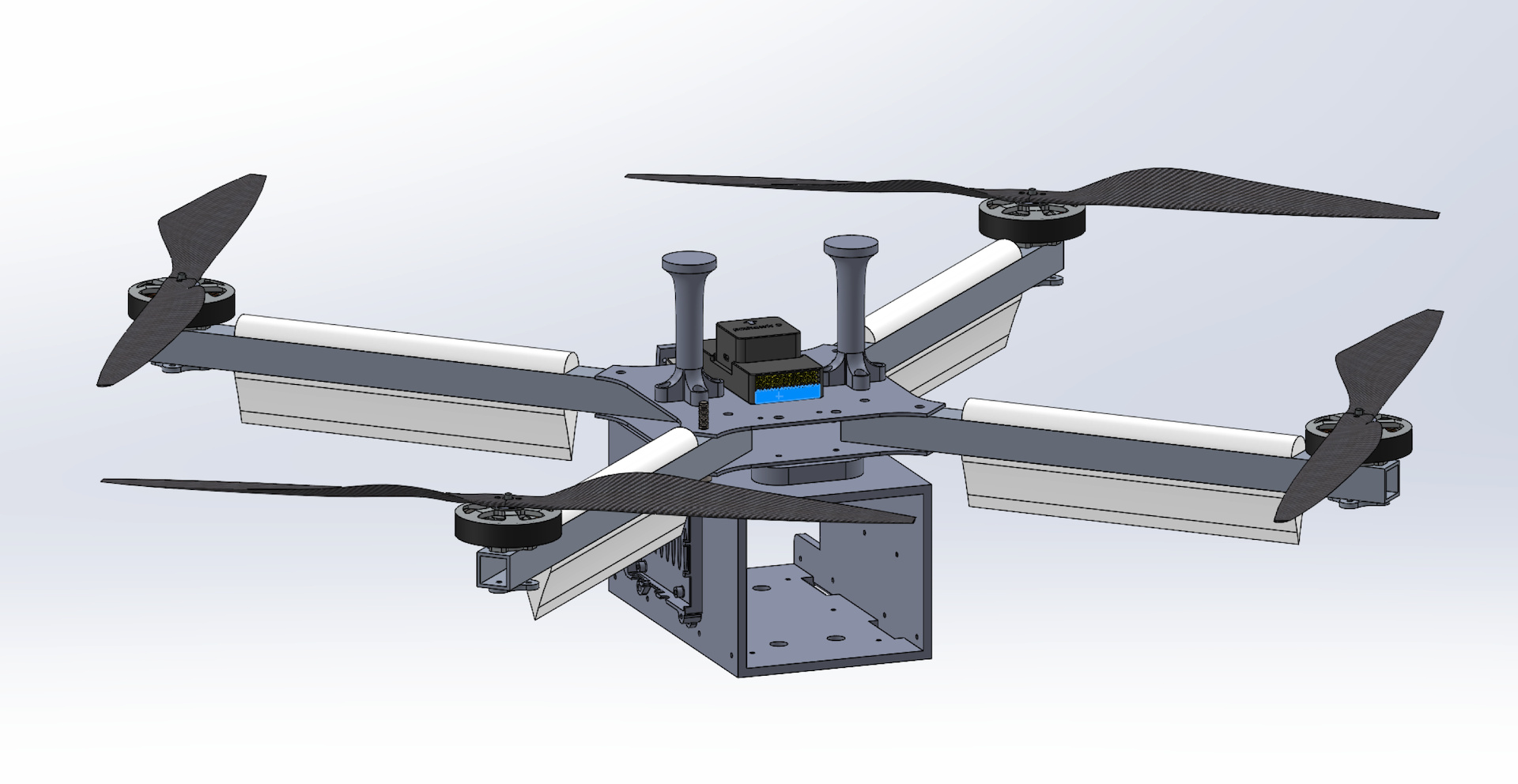
the whole copter with almost correct masses (i’ve imported the motors and props from Grabcad) is drawn in solidworks, i can share the Step and/or solidworks files with you, what do you prefer?
to get this right, you mean i should cover the cube to protect it from wind?
btw for 14m/s pitch is about 9 degrees, but as we want to go even faster yes, maybe we get close to 20 degrees.
we are still trying to find the most efficient speed to get the maximum range out of it…
The assy opens with a slew of over defining Mate errors. It would have to be simplified anyway for frequency analysis. Well, at least for the level of analysis we are talking about here Thanks for sharing, I’ll play around with it in some spare time.
What is the weight of these motors? Also, in the photo it looks like you have another plate sitting on top of the frame plate. Model doesn’t show that.