Hello everyone,
I’m trying to run lidar lite v3 using i2c.
My parameters are set to
RNGFND1_TYPE = 3 “LidarLite-I2c”
RNGFND1_MAX_CM = 2500 (the maximum range the lidar can accurately report in cm)*
*RNGFND1_MIN_CM = 20 (the mininum range the lidar can accurately report in cm)
I connect Lidar’s vcc out to power distrubation board for 5v.
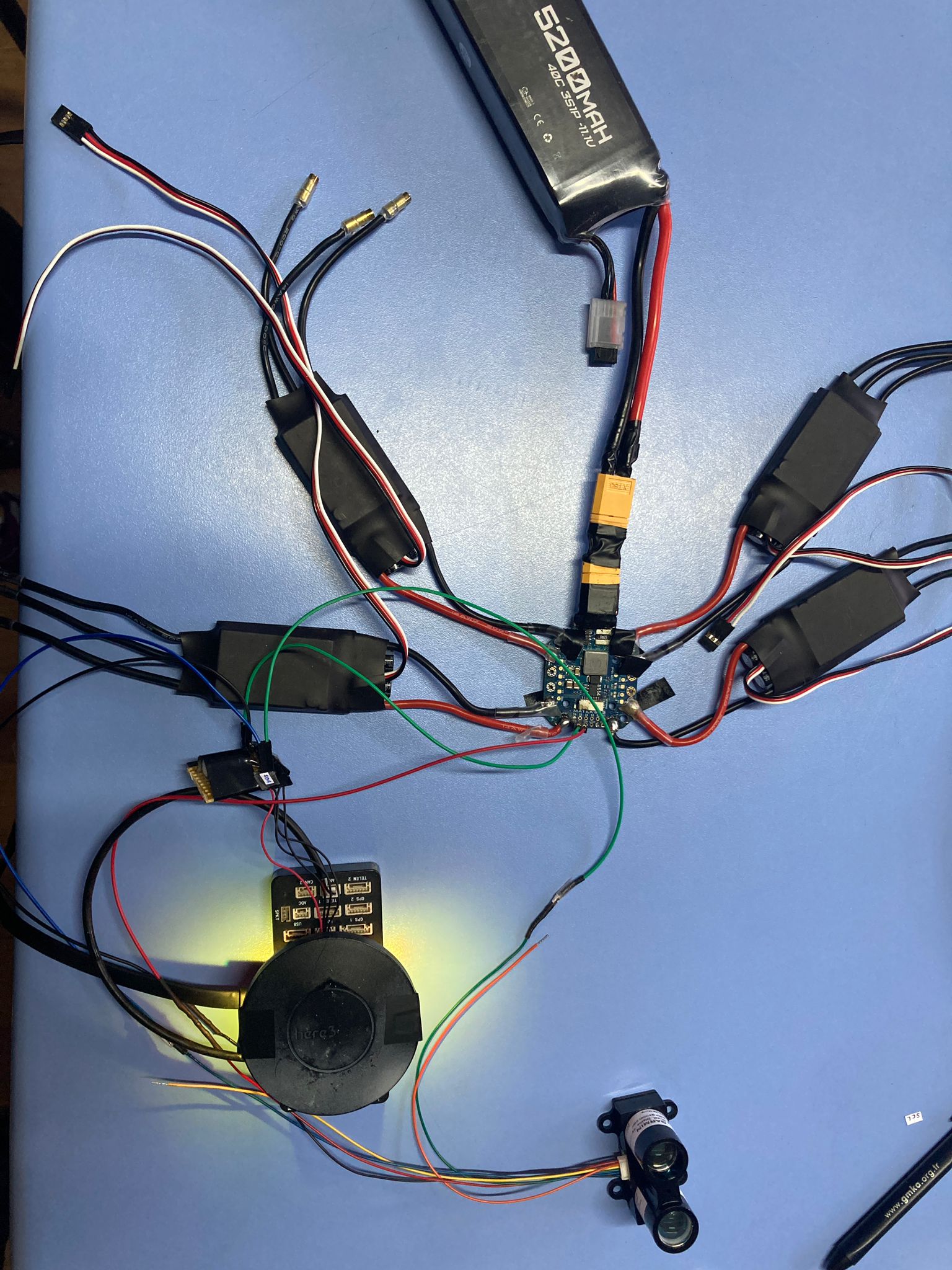
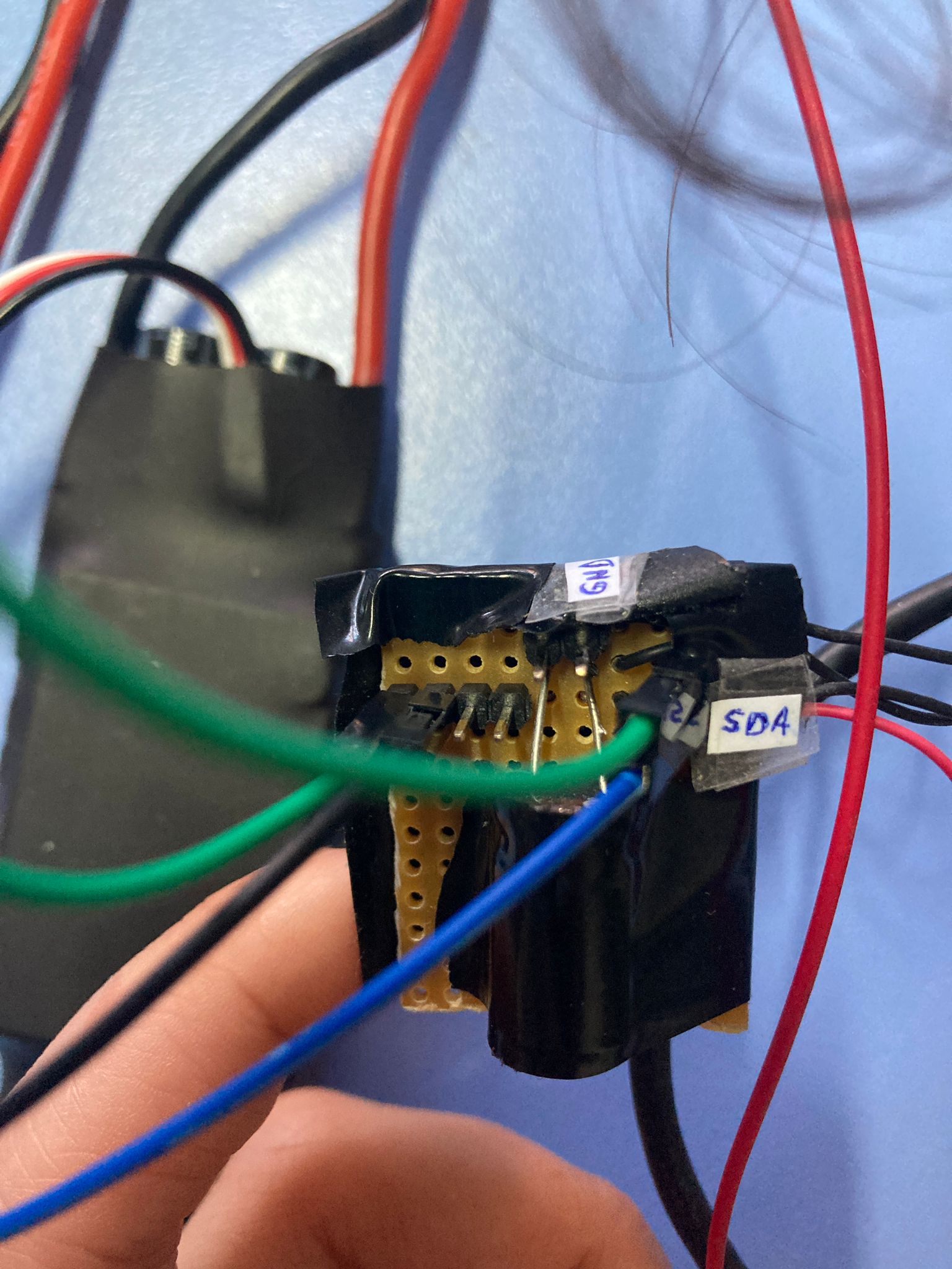
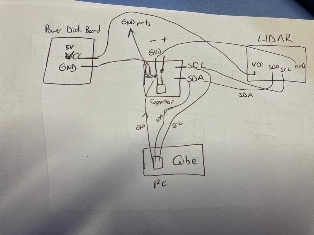
Here’s my connections :
Hard to tell looking at the picture, but make sure the I2C connection is the right order on the CUBE
GND-SDA-SCL-VCC
Vcc is generally the red cable and it is not connected on the configuration (your schematic is OK)
Those wires sure look long. The original wires which come with the Lidar are pretty long.
I don’t know if the wire length is causing trouble but those wires sure make me feel uncomfortable.
Do you have a multimeter? If so, I’d check the voltages on each line. The two I2C lines should idle high. Apparently the Lidar internally uses 3.3V logic levels but the I2C lines tolerate 5V just fine. I’d make sure the Vcc and I2C lines have the expected voltage levels when compares with the ground line.
I’m not sure, but I think any digital camera which can see the IR LED on a TV remote, should be able to see the IR produced by the Lidar. This is what @ppoirier is suggesting.
As another sanity check, you could try connecting the sensor to an Arduino and see if the communication works as expected. Of course if you haven’t used an Arduino before this will likely be more work than you’d want to do.
I think the unconnected cable is actually the orange cable. (I also thought it looked red.)
Thank you for your advices. First of all i shortened the cable. And i changed RNGFND_SCALING → 1. It worked and i measure 35 meters. I checked the purple light too. I understand that advice later. Briefly lidar works. Now i can try lidar and optical flow sensor working at the same time.