Lawnbot with ESPrtk corrections, uBlox ZED-F9P gps, and Cube Orange autopilot

This is mostly a build log so I remember how I built this, and to share setup in order to help others with similar machines.
Part 1 is the ESPrtk base which streams RTCM corrections from a public NTRIP server and broadcasts with a 900 MHZ radio.
Part 2 will be the uBlox ZED-F9P gps setup.
Part 3 will be the Ardurover setup.

The mower I used is an old 21" gas powered push mower, with 8" Hoverboard motors installed for the drive. An Odrive 3.6 56V drives the brushless motors, and power comes from a 36V Lithium eBike battery. Here is a clip of it running with RC transmitter:

5 Likes

Part 1 ESPrtk base.
I chose to use the ESPrtk firmware running on an ESP32-DevKitC V4. This seemed like the quickest way to build a base to send RTK corrections to the mower. The firmware has been in development for a few years and has configuration option for just about any type of caster or rover you want to setup.

I didn’t want to rely on Mission Planner or any other basestation to stream the RTCM corrections to the Lawnbot. The ESP32 boots very quickly and is sending corrections within seconds. Initially I wanted to broadcast with a LORA radio, but the radio I chose (an SX1276 with UART interface) did not transmit the packets reliably. Seemed to be a problem with the 58 byte packets that it transmits.
Switched to mRobotics 915MHz telemetry radios and they just worked…flawlessly.

Here is the schematic of ESPrtk base:

Per the ESPrtk developer, the Minnesota CORS NTRIP server is VRS type, Virtual Reference Station. It requires you to send your GGA coordinates and it responds with the correction. The developer was very responsive in helping me get that sorted and even released an updated firmware due to some of my testing.
Here are a few photos of the construction:


And a video of it in operation:

The ESPrtk has a web interface that makes configuration pretty simple. Here are my config pages:


4 Likes

Part 2 Sparkfun GPS configuration

The GPS module I used is the Sparkfun RTK-SMA with uBlox ZED-F9P.

This blog by Roby was invaluable in figuring out this module:

Sparkfun has great configuration guides which help greatly with figuring out the rather cryptic uBlox u-Center Windows program. I did all setup using u-Center so that I could use the standalone ESPrtk base above for the RTK corrections, rather than allowing Ardurover to autoconfig the gps and send corrections from Mission Planner base station.

Here is my u-Center configurations:

View>Gen 9 Config View>GNSS Config
Enable only GPS L1 L2 & Galileo E1 E5b so chip is not overloaded with data that won’t get used

View>Configure>PRT>
UART1
Protocol in: none
Protocol out: UBX (this is much more compact data than NMEA messages)
Baudrate: 115200

UART2
Protocol in: RTCM3
Protocol out: NMEA
Baudrate: 115200

No NMEA messages are turned on by default,
View>Configure>MSG>
Message F0-00 NMEA GxGGA (GxGLL GxGSZ GxGSVG xRMC GxVTG, these were on but not needed?)
UART2: ON (all interfaces are on by default, can leave checked)

No UBX messages are turned on by default,
View>Configure>MSG>
UART1: ON for the following messages
0A-09 MON-HW, 0A-0B MON-HW2, 01-04 NAV-DOP, 01-14 NAV-HPPOSLLH, 01-07 NAV-PVT, 01-03 NAV-STATUS.
(USB and other interfaces may be on, can leave checked)

Increase location resolving from 1/sec to 5/sec:
View>Configure>Rates>
Measurement Frequency: 5 Hz

To view messages:
View>Messages>Right click on NMEA and UBX and enable

This is great. I’m about to do the same thing.

This is very useful information. I am about to experiment with ESPrtk and this will give me a jump start!

Roland, If you ever want to give LoRa another try, using the Adafruit LoRa Feather M0 works well for me. My code for the transmitter and receiver Feathers is at GitHub - ktrussell/Serial_to_LoRa: Transmit and receive programs for Arduino Feather M0 LoRa module to transmit one way data over LoRa.

BUT, it sounds like the modules you have are working for you and have the range you need.

Roland, U-center and the Ublox configuration is a lot to learn. The good news is that when using it with ArduPilot, we don’t actually have to do any setup. ArduPilot will automatically configure the F9P.

1 Like

Could you please detail how you setup odrive with cube orange? Thanks

Also, just to confirm you’re using only one f9p, correct? Because in the video you said you’re getting correction from f9p.

Ah yes, that would be part 3 that I didn;t get to. I’ll post some details as I get back into the project again. Snow is nearly melted off here in Minnesota :slight_smile:

Yes only using one F9P. Corrections go TO the F9P from the ESPrtk/NTRIP base

Sounds good, looking forward to it. In the meantime do you remember if you did straight pwm signal from pixhawk to odrive or did you do something else?

Hi Roland,
Could you please show me which firmware I should upload to ESP32?
I’m a little bit confused :slight_smile: There are too many options. I would like to use the same configuration as yours/.

Is there the possibility to contribute to esprtk project? I will be interested to build a multichannel server. Which will be sending corrections to multiple f9p modules :slight_smile:

@Piki1989 ESPrtk is capable of sending RTCM corrections from one base to many rovers. Speak to Thai @Develop_ESPrtk to discuss your requirements with him

Hello. 1 ESPrtk can be use as NTRIP Caster server by itself ( no need 3rd server).
1 ESPrtk can feed to 8 rovers NTRIP Client in WIFI mode and 6 rovers NTRIP Client in Ethernet mode.
You can build your own NTRIP Caster with 1 ESP32 , here some post can guide you start :

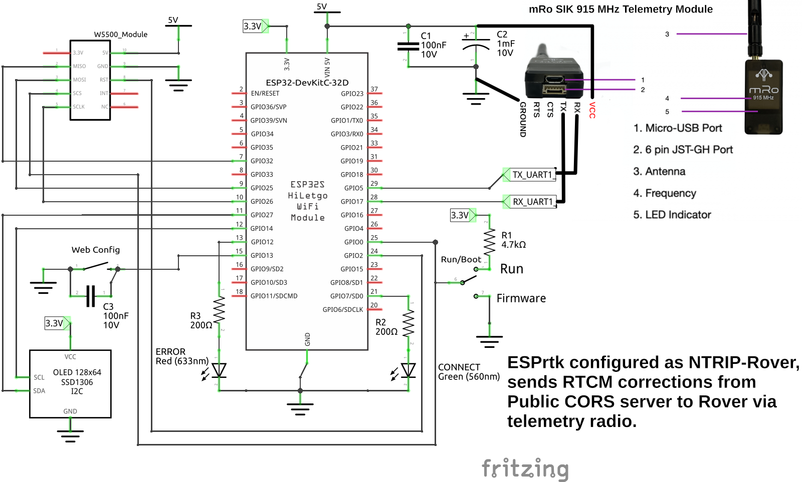
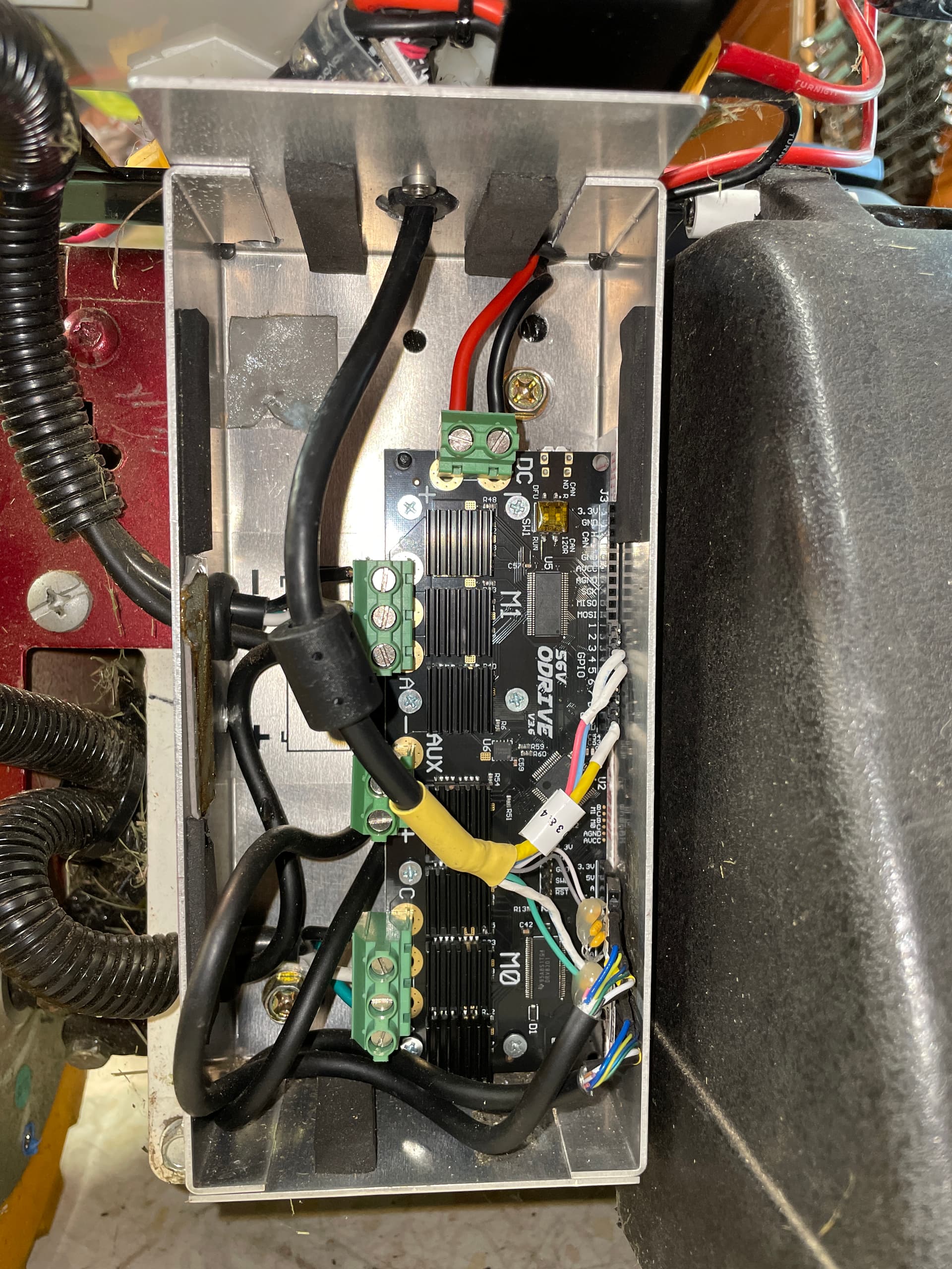
Here are details on the ODrive setup and some Cube Orange/Ardurover setup for it.

Initial ODrive setup was done using the Hoverboard guide on the Odrive Robitics site:
https://docs.odriverobotics.com/v/0.5.4/hoverboard.html#hoverboard-motor-configuration

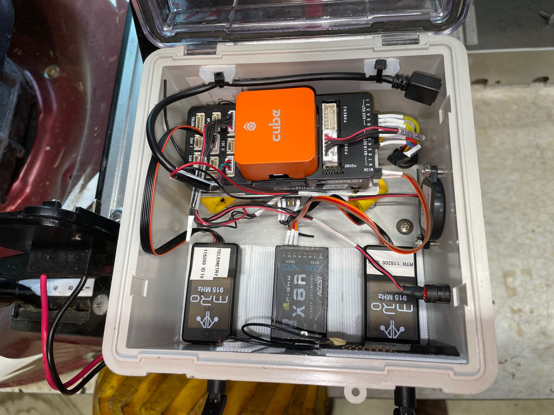
Cube Orange connections to ODrive
(Signal only, ground connection from shared power only to prevent ground loop)

Cube Orange		      Odrive 3.6		Wheel Encoder
(Programmed as inputs)

			          M1 (Left) 5V		Red
			          M1 (Left) A		Yellow	0.1uF to GND
Aux Out 4-------------M1 (Left) B		Blue	0.1uF to GND
Aux Out 3-------------M1 (Left) Z		Green	0.1uF to GND
			          M1 (Left) GND	    Black


			          M0 (Right) 5V	    Red
			          M0 (Right) A		Yellow	0.1uF to GND
Aux Out 5-------------M0 (Right) B	    Blue	0.1uF to GND
Aux Out 6-------------M0 (Right) Z	    Green	0.1uF to GND
			          M0 (Right) GND	Black

Main Out 1		GPIO 4 PWM Left Throttle
Main Out 3		GPIO 3 PWM Right Throttle

Encoder setup in Ardupilot:
Connect motor encoder’s A and B outputs to the autopilot (i.e. Pixhawk’s) AUX OUT 3,4,5 and 6 pins.
Normally 3,4 should be used for the left motor’s encoder, 5,6 for the right’s.

Pixhawk has 6 AUX Ports (AUX1-AUX6, referred to as SERVO9-SERVO14 in Mission Planner)

To use Aux Out 3,4,5,6 to be used as inputs
set SERVO11_FUNCTION, SERVO12_FUNCTION, SERVO13_FUNCTION, SERVO14_FUNCTION as -1

Need to reboot after enabling GPIO’s before WENC2 will be available

set WENC_TYPE and WENC2_TYPE to 1 to enable reading from two wheel encoders
set WENC_CPR and WENC2_CPR to the counts-per-revolution of the encoder. This is the number of “pings” the encoder will produce for each full revolution of the wheel
set WENC_RADIUS and WENC2_RADIUS to the radius (in meters) of each wheel (i.e. 5cm radius would be 0.05)
set WENC_POS_X and WENC_POS_Y to define the first wheel’s distance from COG
set WENC2_POS_X and WENC2_POS_Y to define the second wheel’s distance from the autopilot or COG
disable relays by setting RELAY_PIN and RELAY_PIN2 to -1 (set by default)

Found per Yuri_Rage, Origin is center of drive axle so antenna and encoder offsets are relative to that.
WENC = Left wheel, 0.266M left, 0.330M behind
WENC2 = Right wheel, 0.266M right, 0.330M behind

WENC_PINA = 53
WENC_PINB = 52
WENC2_PINA = 55
WENC2_PINB = 54

EKF Config:
set AHRS_EKF_TYPE to 3 (means use EKF3) default
set EK2_ENABLE to 0 (disable EKF2) default
set EK3_ENABLE to 1 (enable EKF3) default
set EK3_SRC1_VELXY to 7 (“WheelEncoder”) was GPS


Not sure why some of my replies aren’t showing…
Yes, straight PWM, see notes I attached from a week ago

I am using 3.10.00

https://esprtk.files.wordpress.com/2022/06/esprtk_3_10_00_app_0x0.zip

Yes, you need to pay the $50 and register, rather a complex process but the developer email help was very good.

Here’s the process from their site:

http://esprtk.wap.sh/tt/t3/register_update_firmware.html

I’d be interested in seeing the process for registering and loading the FW onto the ESP for 3.10.00 as the written description is very confusing due to not being written for the latest FW. Any chance of sharing the body of the email?
Thanks

Ha, I didn’t mean to imply that he sent me an email that helped with the registering process. As I remember, the documentation on the website was sufficient. The email support was more for configuration, most of which I gave above.

1 Like