Hi, we are building a large 200 lb tricopter drone (15 ft long, 8 ft wide, 5 ft tall). We can not get the pitch PID controller to tune properly. The problem is that the drone is so large that the drone’s fundamental mode of pitch oscillation (~1Hz) is so low that the PID controller treats it as a stick control signal and does not try to correct the pitch oscillation.
Is the anyway to lower the freq responce of the Pitch PID controler so that it can try to connect for oscillations in the fundamental mode of pitch oscillation?
We have tried changing all the PID parameter for weeks. This is not the problem. The problem is that the PID controller is designed not to respond to low freq stick inputs, and our vehicles pitching frequency is so low (~1Hz) that the PID controller thinks it is a stick control signal and does not try to filter it out.
Yes, I followed the directions in tuning guide. The test setup is like a child’s teeter totter and pivoted at its CG. Just like a child pushss up with their legs to get the teeter totter to oscillate up down, I pushed up on one one end of the drone and released it to get it to oscillate up and down.
It is starting to look like the PID controller in ArduPilot can not control larger drones with large rotational rotational inertia very well. Some control is possible, but some residual oscillation in pitch and roll can not be removed. The problem is that the large rotational inertial makes the vehicle slow to respond to motor thrust changes, and this makes if difficult for the PID controller to stabalize. Here is link to an academic video discussing this problem
Refer to 33min into video where they discuss the specific case of an Oscillatory system with dead time between controller output and responce of the measured process variable.
In the video, they show that this type of system can be stabalized much better with a PI-D, and even better with a PI-PD controller.
To verify this idea, using the pitch bench test (ref test 1 above), I disconnected the FC from the motors and operated the motors using just a receiver, and I was able to adjust the balance between the front motors and back motor using a knob on the Tx. The flight controller was still active and able to measure to monitor and log the sensor data. The experiment showed that the observed oscillation was gone and that it was very difficult to manually controll the pitch because of the slow responce of the system.
William
I advise you to go a lot deeper: Use system identification to build a matematical model of the copter.
Once you have done that you can optimize the controller. My guess is that the PID controller of ArduCopter works just fine, if correctly parameterized.
We have done this to our copters and are working as we speak on adding it to ArduCopter’s wiki pages. We will also contribute a simulink model of ArduCopter’s rate controllers.
The methodology allows you to select the desired step response, noise rejection, disturbance rejection and actuator bandwidth. It also gives you the gain and phase margin.
I am very interested in seeing what you have done. Especially how you modeled the system (plant)? And how you used it to design the controller? Lastly, how you implemented it using ArduPilot and a actual flight controller. Please let me know when you have uploaded this to Ardupilots Wiki.
William, i am having some of the same problems. I have a 200lb hex 75in x 90 in. Cant get it tuned good. Not much help out here for the massive drones lol
After some thought, I am starting to see things differently. Orrigionally I thought the vehicle was acting like a resonator and the PID loop was exciting the resonance. But at a few experiments have changed my mind. For instance no oscillations were observed when the flight controller was turned off, but the motors were still running, which suggests the oscillations are being generated by the PID controller. Also no oscillations were observed when flight controller and the motors were disconnected, and the vehicle was pivoted by a more rounded pivot point, which generates no restoring forces resulting in an oscillation. Whereas the more flattened pivot point generated restoring forces resulting in oscillation.
I now think that the vehicle acts more like a rigid beam which simply rotates about it’s CG, and the motors generate restoring forces which, combined with the vehicles rotational inertia, forms a resonator about the vehicles desired balance point.
Out of sync motor thrusts caused by an improperly tuned PID controller, combined with the vehicle’s rotational inertia, results in oscillations of the vehicle about the balance point. Also, imbalances in the motor systems generates noise which gets picked up by the flight controllers sensors and adds noise to the PID loop, which hides the error signals slightly, resulting in slight motor thrust imbalances. So there will always be small fluctuations about the stability point, even if the PID loop is properly tuned. Whereas an improperly tuned PID loop can cause the system to oscillate about the stability point.
I wonder that typical 2 wire hang test for the Inertia around the axes, plus a motor control to thrust curve.
Bear in mind that such large surface and so low to the ground is getting all kind of airflow around it complicating things .
The hover of such vehicles can exhibit drift without tilt ,impossible to measure.
Juan
But, the logs show that the pitch is oscillating a few deg and we want to reduce this. Here is a link to the log of the flight. The last flight corresponds to this video:
As you indicated, ground effect makes the vehicle a little unstable on take off. But as the vehicle gets a few feet off the ground, it begins to stabalize and seems to fly well. So it is best to pop the vehicle quickly on take off. We have also seen this behavior in the 1/6 scale model, which also flys well in VTOL:
I should mention, the observed oscillation is not a pure oscillation. It seems to slowly drift in amplitude. We thought it might be due to ground effect, so we put the vehicle on saw horses, which lifted the vehicle about a foot and a half off the ground. But his did not seem to make a difference. Perhaps it is noise from the motors coupling in through the flight controllers sensors, but we are surprised there would be so much energy at such a low freq (~1Hz), when the motors are at about 6000 rpm. The back motor has 4 blades and this should generate ~25Hz vibrations (ie 6000/4/60=25). Perhaps their are nonlinearities in the system that are lowering the frequency.
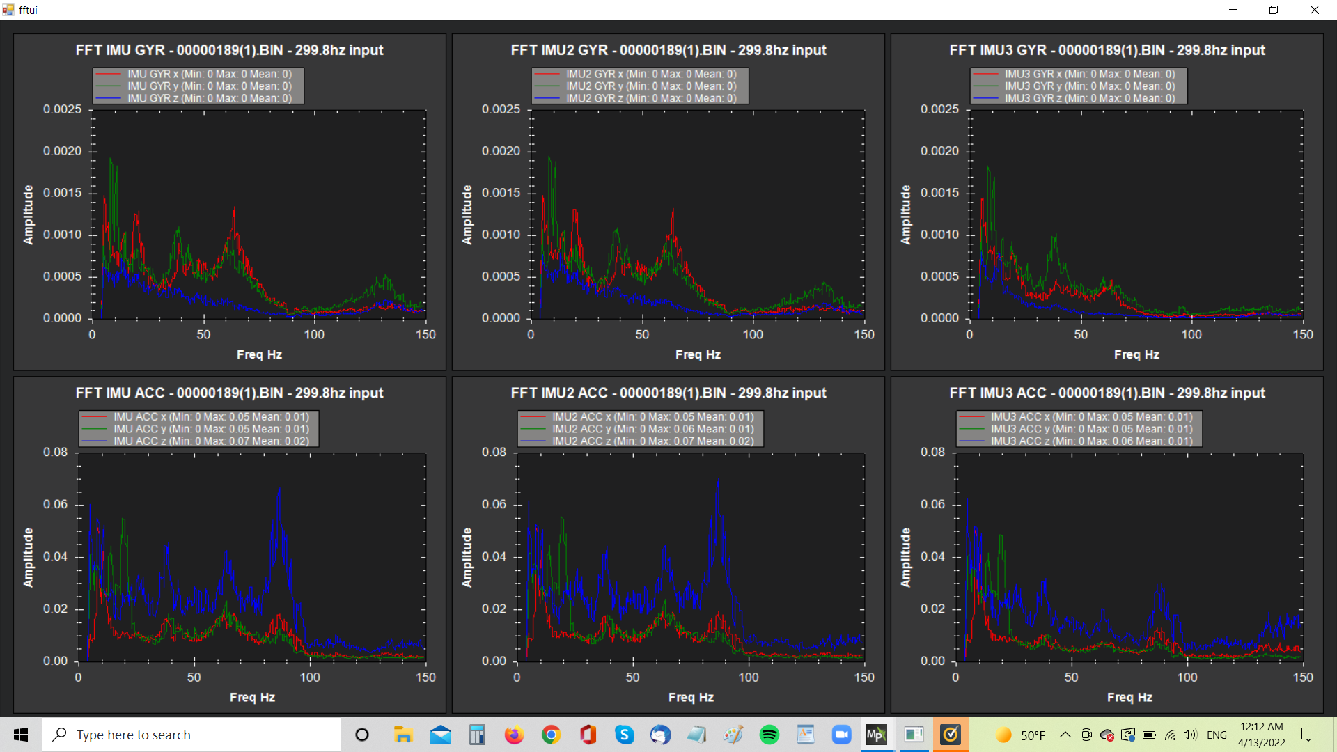
Is it possible the motor noise is alaising to the observed oscillation frequency (~1Hz) due to the limited sampling time of the Pixhawk cube Gyro sensor. This would account for the observed wandering amplitude oscillation. The back motor is operating at ~6000rpm and it is using a 4 bladed prop. So the fundamental motor noise is at ~25Hz (ie 6000/4/60= 25). But it could be rich in harmonics which can alias beyond the Nyquist freq (~500Hz).
As I mentioned, there is probably a lot of vibration coming from the back motor unbalanced prop, which is very close to the FC. This I think is the problem, and the higher harmonics are aliasing to the vehicles oscillation frequency.