No, haven’t installed such a thing but my daily work involves all sorts of technology (electrical / electronic control systems).
In an electric powered vehicle:
Install a relay in the power line powering the motor. If bumper switch is activate power to motor is being cut.
In a heavier vehicle: Use a relay to short circuit motor wires (whist disconnecting supply line) in order to get an electric brake effect.
In a Petrol / Diesel powered vehicle: Use a fuel solenoid shut-off valve to cut fuel supply or if possible disengage drive system.
I would not rely on the control circuit / electronic as this may proof un-reliable as seen with the Toyota Prius back in 2009/2010 where their system caused multiple deaths.
1 Like
Well I am making progress on my mower build and I just wanted to post a few pictures of my Base Station. It has been a long haul to start from scratch to build an autonomous mower. When I started this project several years ago I told @ktrussell that I would share some pictures and I plan to post hardware pictures in the coming month. I my mower is starting to come together and I just wanted express my appreciation to all the people on the blog site that have helped me.
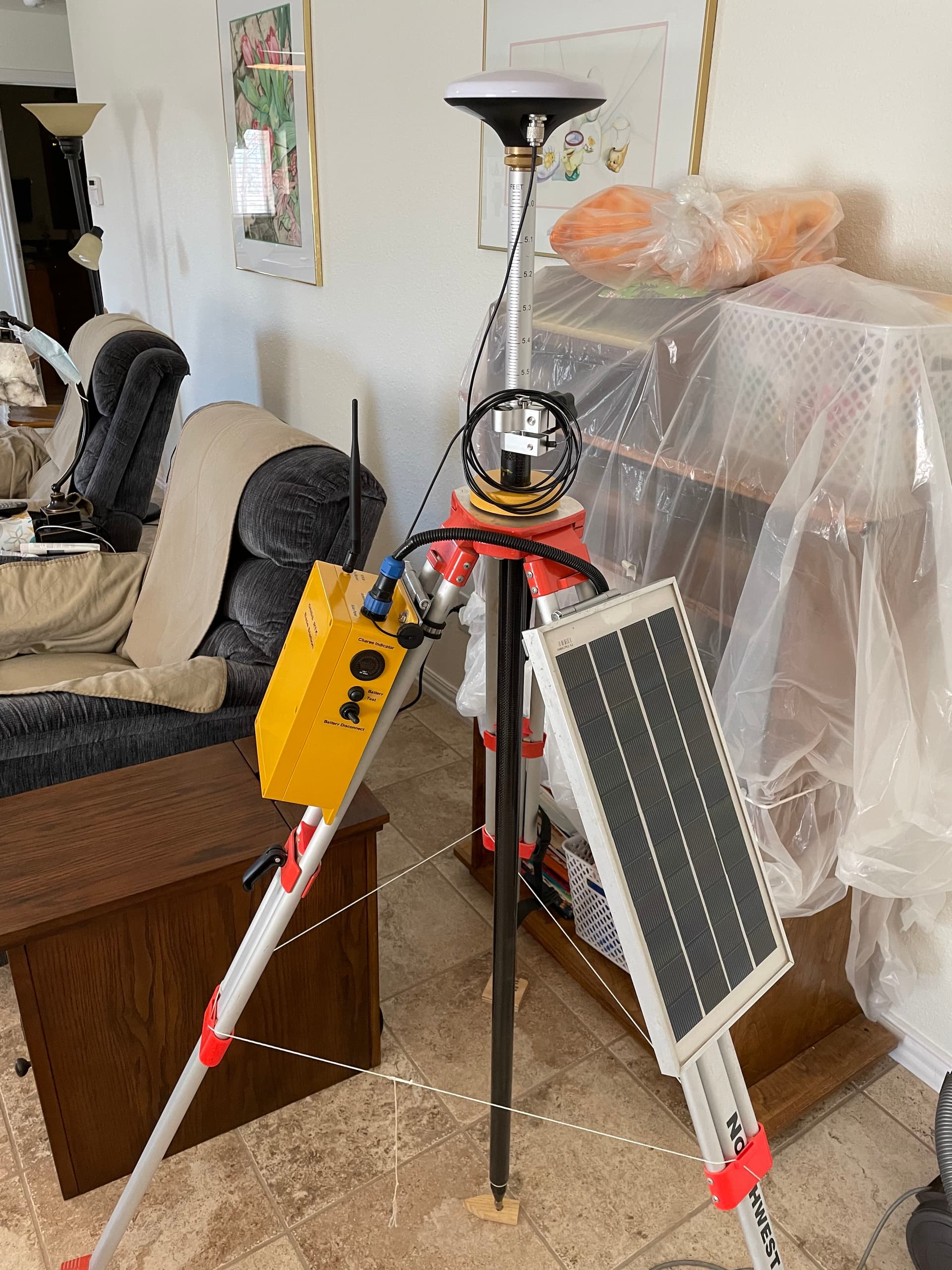
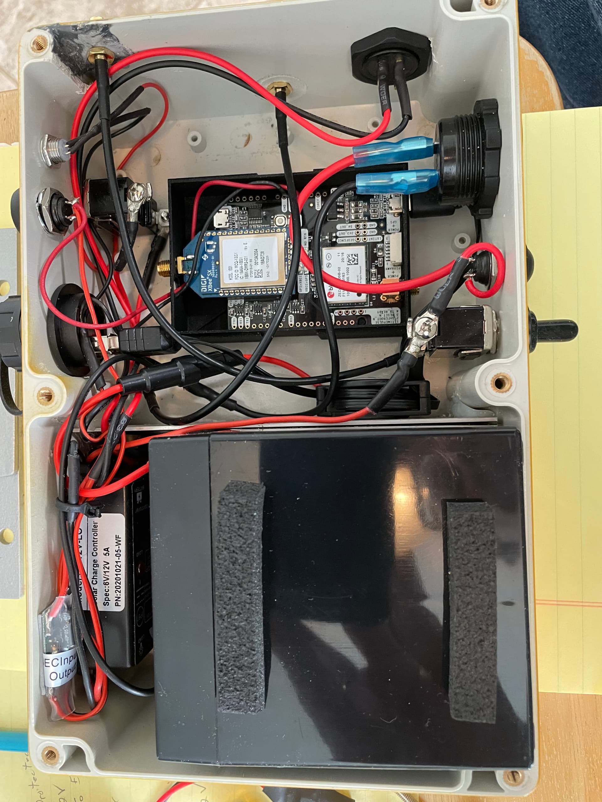
The Base Station was tested on the bench top with the U-Center software from UBox and it shows its working. I am just missing the right angle antenna connectors to allow the F9P board to fit in the box and it should be good to go.
A basic overview of the unit:
Portable, maintain it’s own power source, be able to connect via USB without opening the lid, and last but not least send RTCM correction signals directly over to the mower using the piggyback X-bee radio on the Ardusimple GPS board. I am not using Mavlink to do the RTCM injection.
Next time I’ll post pictures of my servo mounting on the hydraulic control valves under the mower, it has been a challenge, but I have tried to learn from all that has been learned by the many people on the blog site (and my own mistakes).
4 Likes
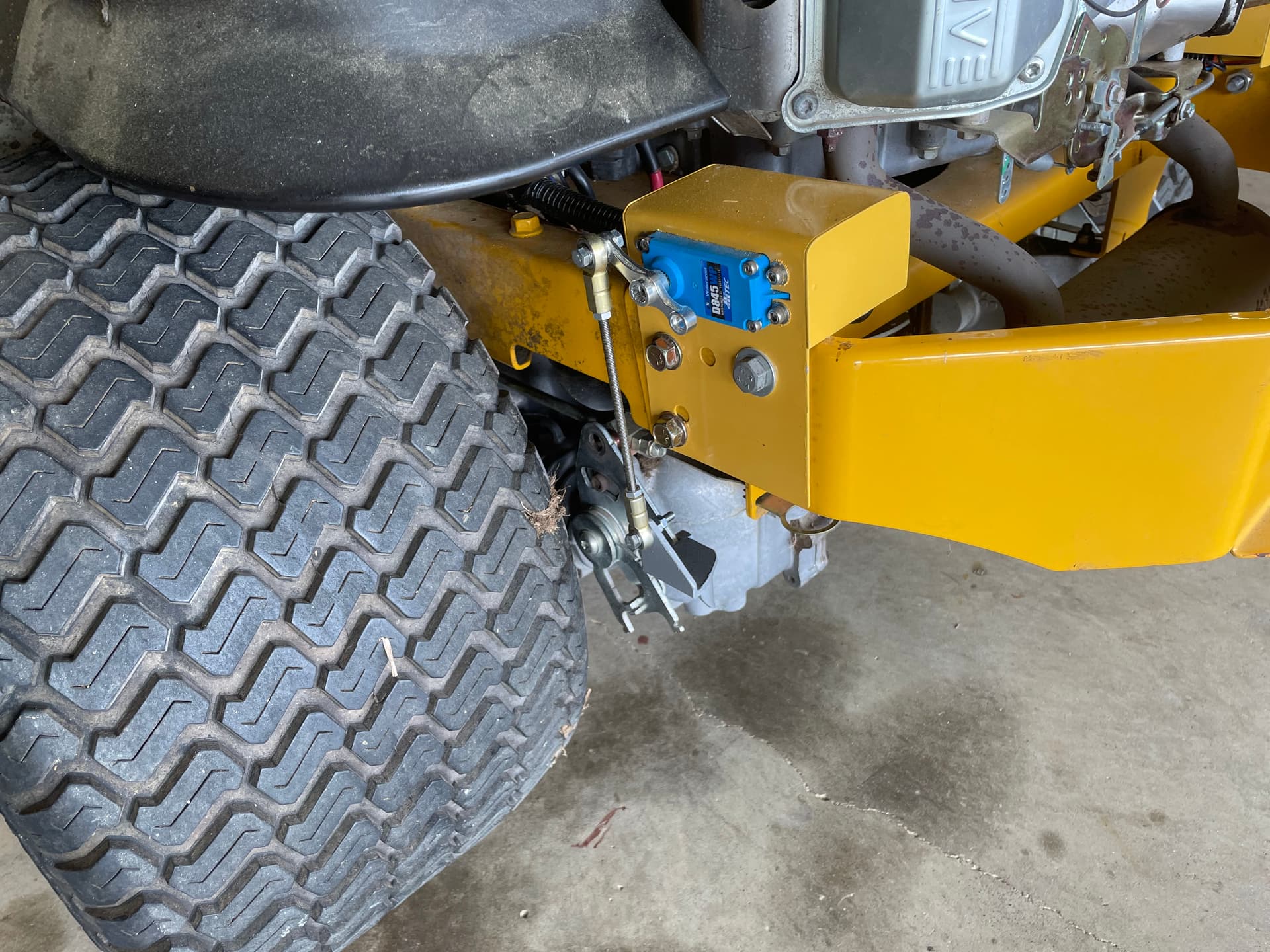
Pictures of the servo mounting.
I have finally gotten my mower to the point I can drive it with the RC controls going through the orange cube. It is tuned pretty well and easy to drive. That was a milestone and at least now I have a solid start to move ahead in activating the RTK GPS systems. The cube is in the center enclosure on the top of my electronics rack.
I also proudly display the Ardupilot sticker on my machine!
1 Like
Well done! I need some ArduPilot swag for my own!
Those look like HydroGear transaxles, which are a great candidate for automation. The control linkage doesn’t require too much torque to move.
There’s another style (I forget the brand) that have linear rods that enter the transaxle housing from the manual control linkage. They really load up when hydraulic pressure is applied, making the drive servo torque requirement very high, and thus very expensive.
1 Like
I have a question related to protecting the sensitive electronics like the flight controller from the electrical noise environment of the mower 12v power system. I am just concerned about the spark plugs firing and the surges from the starter starting . So far I have been running my electronics on a completely separate battery, but it does require me to keep it charged up. Am I just worried too much? Does the flight controller need to be on isolated power? What are the other zero turn mower builders doing in terms of powering the sensitive electronics? I am powering my large servos from the mower power system isolated using the ProTek servo rail isolator (the 12v is stepped down to 5v for servos). The orange cube, the long range radio, GPS cards, and the other small stuff only seems to draw about 1/2 an amp and I keep them on an isolated power. Right now my system is very stable and reliable so I am hesitant to change it, except I don’t like charging the extra battery.
I use a Mauch power module connected to the mower’s charging system to supply the 5V required. Never had a problem with that. I also used the stock power module that comes with the Cube for quite a while and had no issues, but the Mauch unit is more robust and has some extra sensing features that I like.
You’re not wrong to be concerned, but I think you’re a bit over-cautious with complete isolation like that.
1 Like
Hey Steve. I’m powering the mowers main electronics off a Holybro PM and the servo rail by a Castle BEC both connected to the mowers battery and charging system. I monitor the servo rail and board voltages during missions and they seem to vary less than 0.07V overall, with the greatest fluctuations seen on the servo rail during turns. Have not put a scope on the 12V system looking for pulses/spikes (and I’m sure some are there) but mower seems happy. Have you put a scope on your charging system?
1 Like
I upgraded the stator on my Kawasaki engine for increased output after adding a bunch of servos for choke, engine throttle, and parking brake, along with some headlights. The stators for the FR series engines come in two flavors - 13A and 20A but have the same mounting configuration (just more windings).
After that, I started blowing out those cheapie voltage regulators that are stock on those engines, so I’m now using a big rectifier and smoothing capacitor fed into a beefy stepdown converter. Scope shows pretty reasonable results, with some expected noise, but no major spikes or worrying inconsistencies. I actually tried to make a YouTube video of the upgrade process, but the footage turned out terrible, and I abandoned it.
I didn’t put a scope on the stock setup, but I’m sure it was noisier, and I never had a problem powering the autopilot electronics.
1 Like
Thanks so much for sharing your experiences. I don’t have a scope and I really don’t know how much noise I have on the 12V mower electrical system. I was just being extra careful based on earlier experiences when one of the members lost an Orange Cube to noise spikes. It sounds like I can probably switch things around and use the mower electrical system with the right power supplies where the servos remain on a different BEC than the one powering the flight controller.
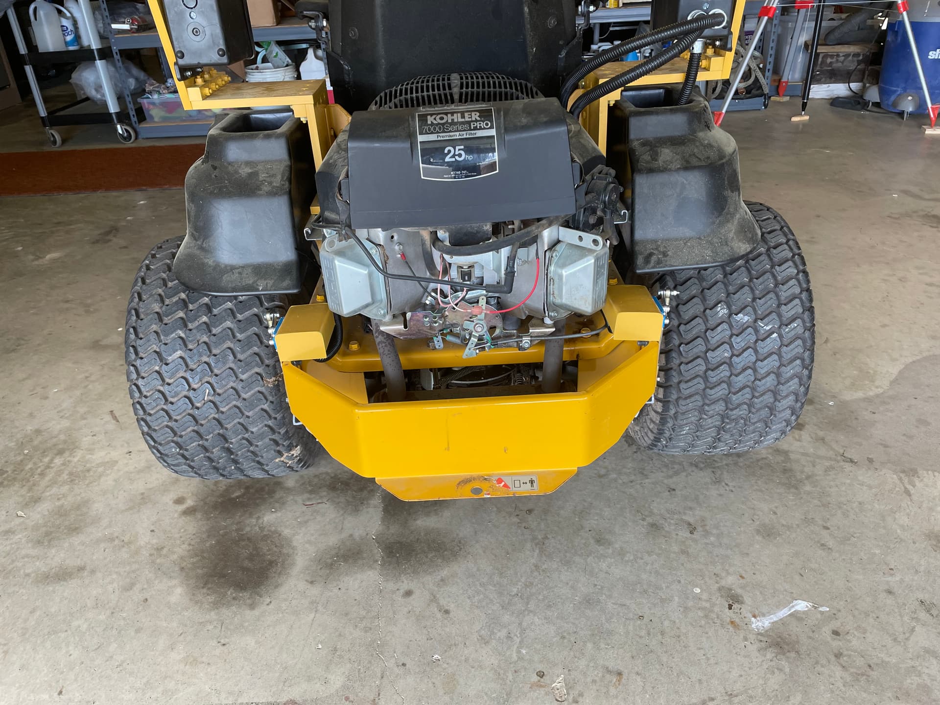
Do you know if they make larger stators for the Kohler zero turn mower engines? I hope I have enough power on the stock setup but time will tell. I think I have a 25hp Kohler engine.
I don’t know that. I’m not much of a small engine expert, and sort of just stumbled into the “upgrade” part for the Kawasaki FR engines.
Once the main battery is charged, the amps needed for the guidance system itself is pretty small (<2 amps). And since there are routinely only 2 servos active at any one time (Choke/Start, Right/Left, Steering/Throttle, etc) their draw should be minor also unless you are using honking big ones and they are in a bind. I’m guessing that during a normal mission, the whole control system is using <4 amps while going straight. My LED lighting and a slight charge should put the whole load about 5-8 amps…or less.
1 Like
All so very true!
I have some “big honking” servos, including one on the combustion engine throttle that’s constantly working against a hefty governor spring, which, combined with the PTO clutch, puts a strain on the stock electrical system.
When I was blowing out voltage regulators, I was also using multiple buck converters, and the throttle servo was smaller, working off of a converter that probably wasn’t very efficient. I’m now using all 12V servos with none of those converters in the loop, and I suspect that the entire system is much happier, though I haven’t measured overall current draw to prove it.
Had the same issue with the throttle servo. On our mower, the Kawasaki FH580 has a serious throttle return spring. After a long mission, the servo temp was over 140F from fighting that spring. Didn’t have another original size spring to modify, so I added a spring to “help” the servo. Servo runs “cool” now. Going to a larger/higher voltage servo is a good decision and my next step if more problems occur.
The mower’s system voltage starts out at ~14.3V right after start-up and drops to ~13.5V by the end of a long mission (2+ hrs).
Hey Steve - Not sure exactly which model Kohler you have but the newer 25 hp ones usually have a 20 amp charging system. I’m thinking you’re good!
1 Like
I removed the throttle return spring entirely, but the throttle lever acts against a governor mechanism with a big spring, and I haven’t quite worked out how to lessen that pain. I’d rather not have a “helper” spring acting in the opposite direction, which might cause a full throttle condition if the servo fails.
I’m using one of these now, which, despite its size, is quite powerful. It gets a bit heated under heavy use, but I have a good number of hours on it now without sign of failure.
These are my drive servos. I had one fail early on, which may have been the result of a position controller (SCurve) D gain tuning value that got out of control and caused a lot of oscillation…or it may just be that Chinese quality control is…as it ever was…
Overall, I do like these servos, and except for that one failure, they have been performing quite well.
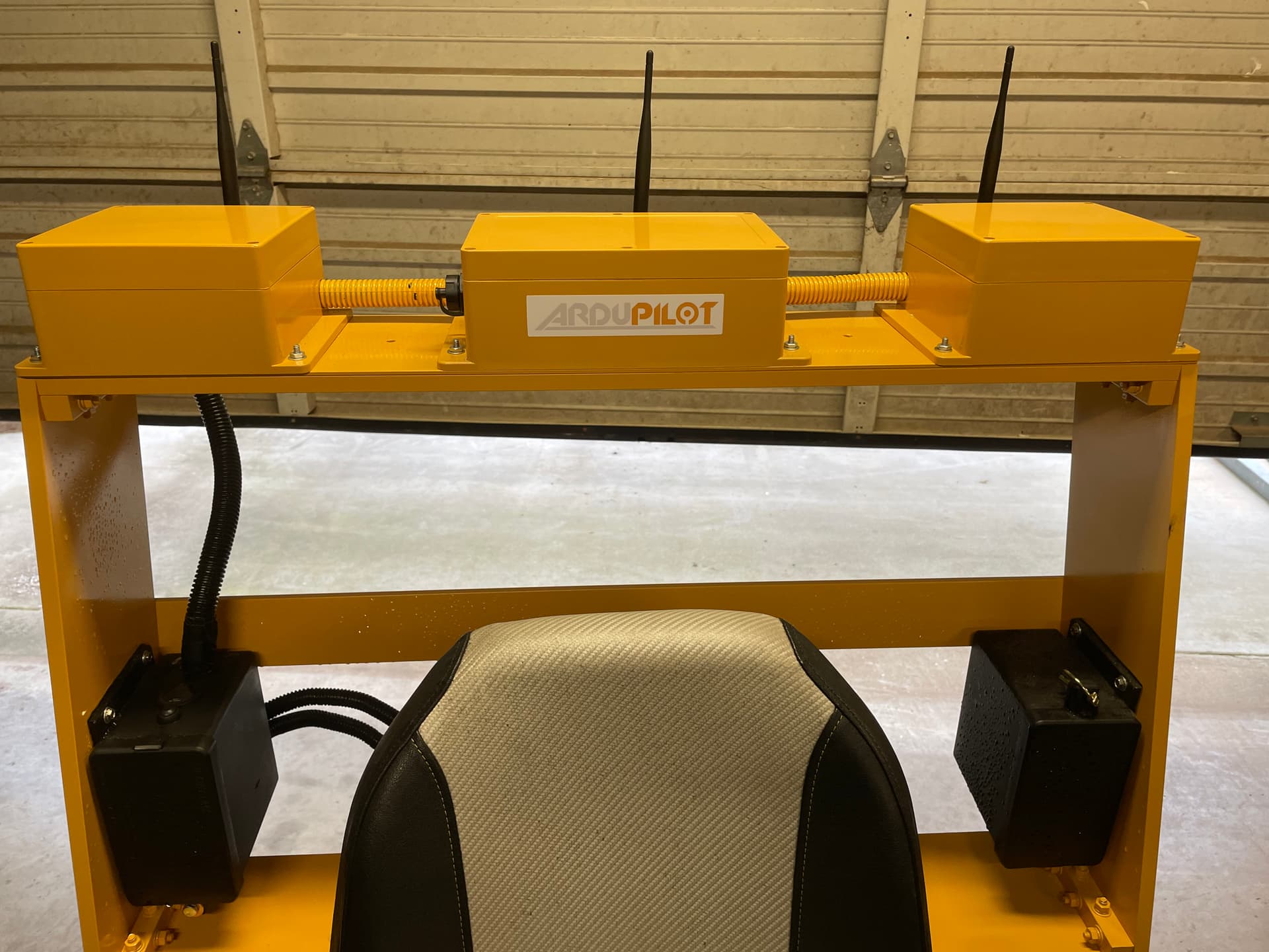
I just wanted to continue to share more pictures of my work so far. I have enjoyed this project greatly, even though I do not have it completed yet. Maybe more pictures will help motivate others to join us in building these machines.
My electronics are housed in 3 boxes mounted on an aluminum structure behind my seat. I decided to leave my seat on for now.
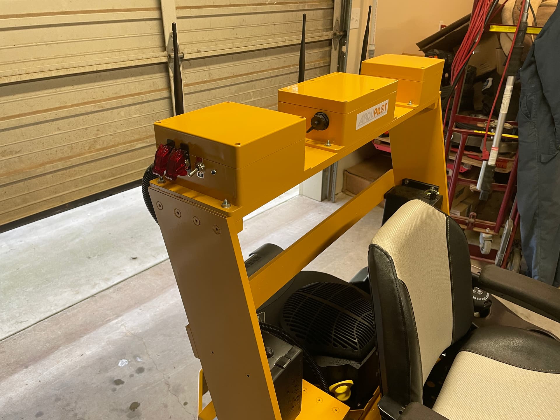
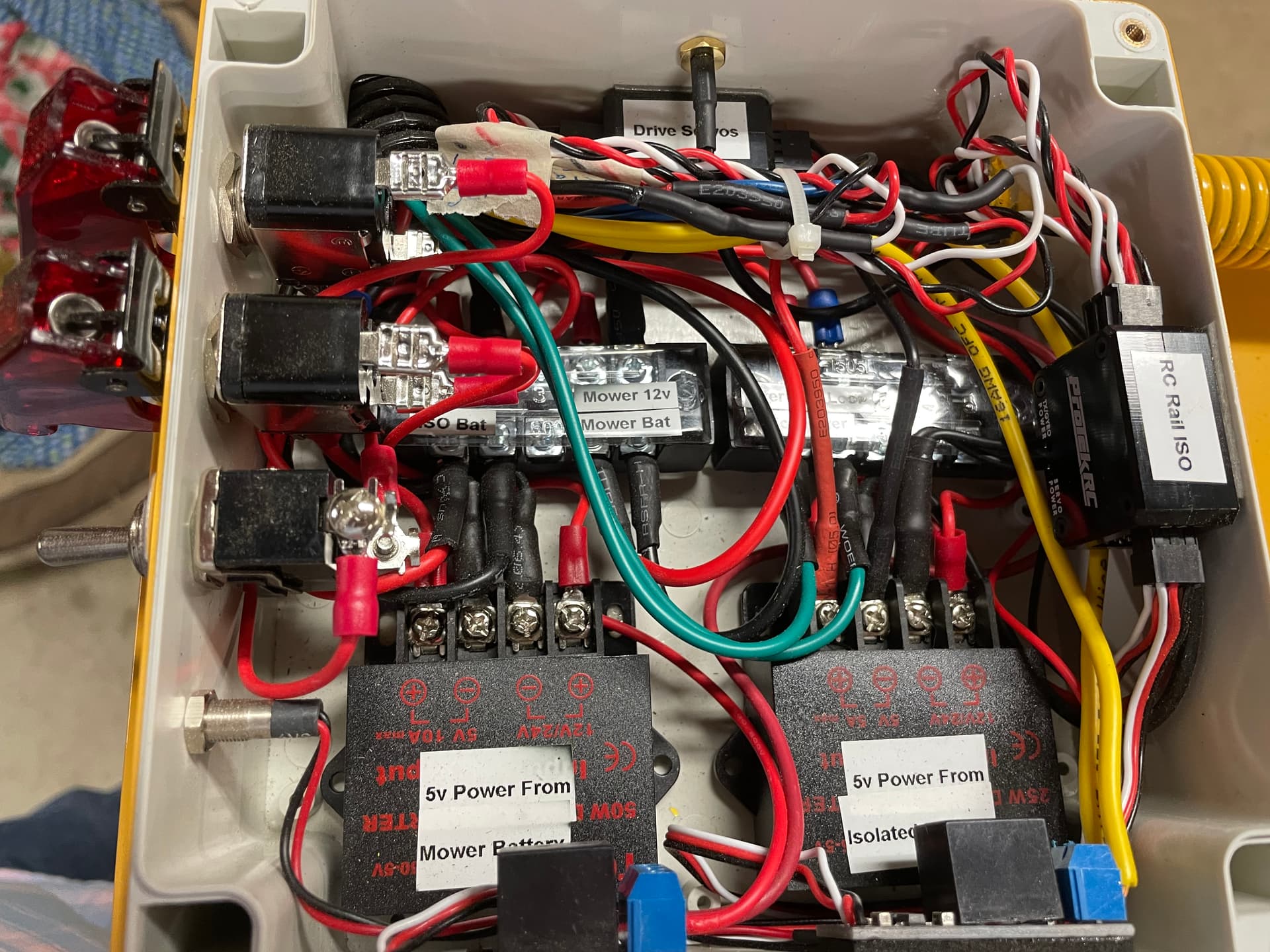
Here is a picture of my power distribution box. It houses 2 robust BECs, power distribution, Pixhawk rail isolator, radio receiver rail isolator, a radio controlled emergency kill switch, a radio controlled starter relay, as well as switches and indicator lights.
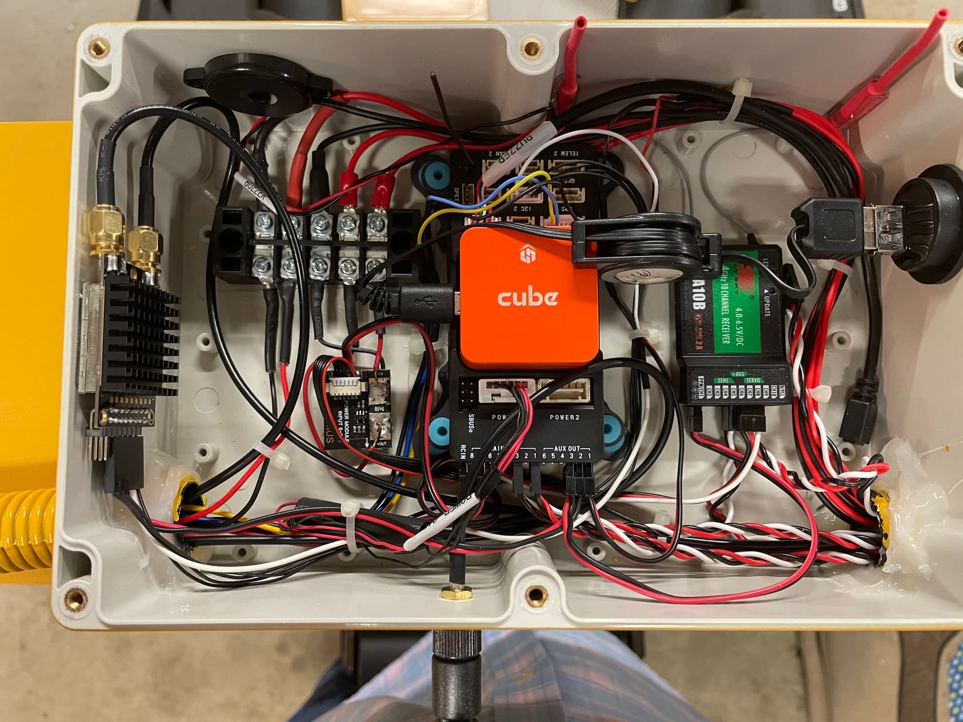
The next box contains the Orange Cube, The RC receiver, a dedicated BEC (which allows voltage monitoring), and the RFD900 long range radio. I also chose to mount my flight controller on a mechanical isolation mount to absorb some of the rough ride it will get out here on the farm.
Later I will share the third box where the 2 GPS units and the radio that receives the RTCM correction signal will be located. This part is still in work. The 2 GPS satellite antennas will mount on top of the outer enclosures.
2 Likes
Hey Yuri - The helper spring I installed doesn’t counter the stock return spring completely. Just lessens the servo load substantially. Throttle is still fail safe to idle if things come apart.
After looking at those links, you have some serious servos! Wonder what the MTBF is for a quality servo? Been looking and yet to find any reliable info. Do know that the folks that fly the high dollar RC jets stick with the big name brands. Futaba seems to get the nod around here. Guess we will all find out as we put the hours on our mowers. Onward!
Oh, your pocketbook is the only limit when it comes to servos!!!
1 Like
LOL! Like most toys in our lives…
1 Like