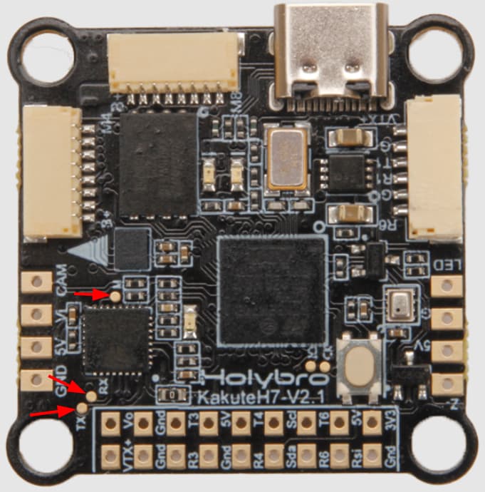
I’m try to reflash ES32-C3 on KakuteH7v2 for compatible with ArduPilot GCS (default FW compatible with SpeedyBee only and have not serial port in bluetooth) but unable to find suitable pads for this task. What do you think these pads are needed:
Hi, my post may not be helpful to the original poster, but I have been searching for the same thing for the SpeedyBee F405 V4, and it led me here and nowhere else. So, this might help someone.
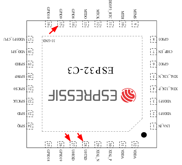
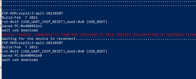
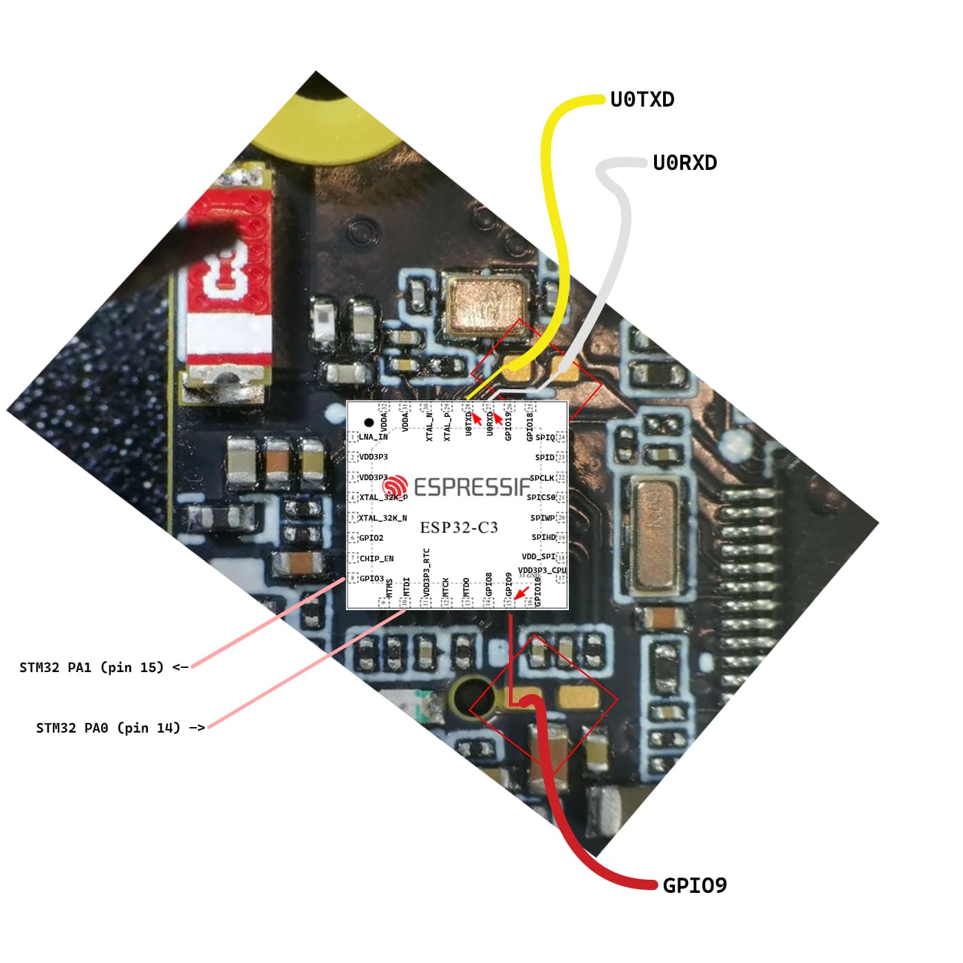
I have been successful in re-flashing the ESP32-C3 on the SpeedyBee board with DroneBridgeESP32 firmware. I soldered UART Tx, Rx, and GPIO9 to GND and powered it up. Unfortunately, I did not save the first boot log, but unlike the original poster, mine showed another boot method and was ready for upload via serial. So, I closed the serial terminal and ran esptool. It went smoothly, and now I am running DroneBridgeESP32 on the SpeedyBee board. I had to reverse engineer the connection of UART between the ESP32 and STM32F405. It is connected as follows:
@kolin I was also looking for a guide on how to flash the SpeedyBee board with the ESP32-C3. Could you share the link to the original post? I will also follow the guide you mentioned. Have you managed to back up the default firmware running on the SpeedyBee ESP32-C3?
Hi, I actually didn’t follow any guide. I worked through the process on my own due to the lack of available guides and shared my experience here. Unfortunately, I didn’t back up the default firmware before flashing the new one. I do not think it was even possible to back up the original firmware. I have not checked, but they may have their firmware locked for reading as usual.
If you have any specific questions about the steps I took, feel free to ask!
Flashing the ESP32-C3 is easy:
Solder three wires to the SpeedyBee: UART RX, UART TX, GPIO9.
Connect it to a USB-UART converter (Rx, Tx, GND).
Start a serial terminal at 115200 baud and the correct COM port.
Temporarily connect GPIO9 to GND.
Connect power to the board (via USB cable, do not use a battery).
Observe the serial terminal; there should be some info from the ESP chip.
Disconnect GPIO9 and leave it floating.
Close terminal and start the DroneBridge web flasher or flash manually via esptool.