The Betaflight mappings for the GF16 are available here:
I have a GF16 stack on-order that should be arriving this week. Draft hwdef.dat attached, I’ll submit a PR once I have received the board and confirmed everything is working. Should be able to support bidirectional DShot on Motor outputs 1-4, and DMA on U(S)ARTS 1, 3, and 6. PWM output 5 may be unusable if you are using DShot, as it shares a timer with M1 and M2. There are a few different ways this target can be configured depending on your requirements, but I figured the default target should support the bundled 4in1 ESC.
# hw definition file for processing by chibios_pins.py
# JHEMCU GF16 by V-22
# With F405 MCU, MPU6000 IMU and MAX7456 series OSD
# Based on Mamba F405 hwdef from jeanphilippehell
# thanks to betaflight for pin information (https://github.com/betaflight/unified-targets/blob/master/configs/default/JHEF-JHEF405PRO.config)
# Board info https://github.com/jhemcu/FC-ESC-Firmware/tree/main/GF16-F405%26ESC

MCU STM32F4xx STM32F405xx

# board ID for firmware load
APJ_BOARD_ID 1060

# crystal frequency
OSCILLATOR_HZ 8000000

# board voltage
STM32_VDD 330U

# need to use timer 2 so timer 5 is available for bidir DShot
define STM32_ST_USE_TIMER 2

# order of I2C buses
I2C_ORDER I2C1

# order of UARTs (and USB)
# this order follows the labels on the board
SERIAL_ORDER OTG1 USART1 USART2 USART3 UART4 EMPTY USART6

# The pins that USB is connected on
PA11 OTG_FS_DM OTG1
PA12 OTG_FS_DP OTG1

# USB detection
PA8 VBUS INPUT OPENDRAIN

# USART1 (DMA) - RCinput through pads TX1/RX1 or SBUS
PB6 USART1_TX USART1
PA10 USART1_RX USART1
define HAL_SERIAL1_PROTOCOL 23

# USART2
PD5 USART2_TX USART2 NODMA
PD6 USART2_RX USART2 NODMA

# USART3 (DMA) - Use for GPS as it is close to I2C pins.
PB10 USART3_TX USART3
PB11 USART3_RX USART3

# UART4
PA0 UART4_TX UART4 NODMA
PA1 UART4_RX UART4 NODMA

# USART6 (DMA)
PC6 USART6_TX USART6
PC7 USART6_RX USART6

# analog pins
PC3 BATT_VOLTAGE_SENS ADC1 SCALE(1)
PC2 BATT_CURRENT_SENS ADC1 SCALE(1)

# RSSI analog input
PC0 RSSI_ADC_PIN ADC1 SCALE(1)
define BOARD_RSSI_ANA_PIN 12

# Motor outputs on AIO ESC
PB0 TIM3_CH3 TIM3 PWM(1) GPIO(50)
PB1 TIM3_CH4 TIM3 PWM(2) GPIO(51) BIDIR
PA3 TIM5_CH4 TIM5 PWM(3) GPIO(52) BIDIR
PA2 TIM5_CH3 TIM5 PWM(4) GPIO(53)
PB5 TIM3_CH2 TIM3 PWM(5) GPIO(54)
PB7 TIM4_CH2 TIM4 PWM(6) GPIO(55) NODMA
PC9 TIM8_CH4 TIM8 PWM(7) GPIO(56) NODMA
PC8 TIM8_CH3 TIM8 PWM(8) GPIO(57) NODMA

# Assign timer to LED_STRIP
PA9 TIM1_CH2 TIM1 PWM(9) GPIO(58)

DMA_PRIORITY SPI1_RX SPI3* USART3* USART6* TIM1_CH2
DMA_NOSHARE USART1* TIM5_UP

# Board LEDs
PC14 LED1 OUTPUT LOW GPIO(1)
PC15 LED2 OUTPUT LOW GPIO(2)
define HAL_GPIO_A_LED_PIN 1
define HAL_GPIO_B_LED_PIN 2

# Buzzer
PC13 BUZZER OUTPUT GPIO(80) LOW
define HAL_BUZZER_PIN 80
define HAL_BUZZER_ON 1
define HAL_BUZZER_OFF 0

# I2C1
PB8 I2C1_SCL I2C1
PB9 I2C1_SDA I2C1

# SPI1 - Internal IMU
PB12 MPU6000_CS CS
PA5 SPI1_SCK SPI1
PA6 SPI1_MISO SPI1
PA7 SPI1_MOSI SPI1
# IRQ for MPU6000
PB13 EXTI_MPU6000 INPUT

# SPI3 - OSD + 8MB flash
PC10 SPI3_SCK SPI3
PC11 SPI3_MISO SPI3
PC12 SPI3_MOSI SPI3
# OSD max7456
PB14 OSD_CS CS
# Dataflash 8MB on-board
PB3 FLASH_CS CS

# SPI Device table
SPIDEV mpu6000    SPI1 DEVID1 MPU6000_CS MODE3 1*MHZ 4*MHZ
SPIDEV dataflash  SPI3 DEVID2 FLASH_CS   MODE3 32*MHZ 32*MHZ
SPIDEV osd        SPI3 DEVID3 OSD_CS MODE0 10*MHZ 10*MHZ

# One IMU rotated in yaw
IMU Invensense SPI:mpu6000 ROTATION_YAW_90

# Probe for I2C BMP280, but allow external baro
BARO BMP280 I2C:0:0x76
define HAL_PROBE_EXTERNAL_I2C_BAROS

# no built-in compass, but probe the i2c bus for all possible
# external compass types
define ALLOW_ARM_NO_COMPASS
define HAL_COMPASS_DEFAULT HAL_COMPASS_NONE
define HAL_PROBE_EXTERNAL_I2C_COMPASSES
define HAL_I2C_INTERNAL_MASK 0
define HAL_COMPASS_AUTO_ROT_DEFAULT 2

# enable logging to dataflash
define HAL_LOGGING_DATAFLASH_ENABLED 1

define HAL_STORAGE_SIZE 15360
STORAGE_FLASH_PAGE 1

# flash size
FLASH_SIZE_KB 1024
# reserve 16k for bootloader and 32k for flash storage
FLASH_RESERVE_START_KB 48

# define default battery setup
define HAL_BATT_VOLT_PIN 11
define HAL_BATT_CURR_PIN 13
define HAL_BATT_VOLT_SCALE 11
define HAL_BATT_CURR_SCALE 17

# Setup for OSD
define OSD_ENABLED 1
define HAL_OSD_TYPE_DEFAULT 1

# Font for OSD
ROMFS_WILDCARD libraries/AP_OSD/fonts/font*.bin

# -------reduce max size of embedded params for apj_tool.py
define AP_PARAM_MAX_EMBEDDED_PARAM 1024
define HAL_WITH_DSP FALSE

# --------------------- save flash ----------------------
define HAL_BATTMON_SMBUS_ENABLE 0
define HAL_BATTMON_FUEL_ENABLE 0
define HAL_PARACHUTE_ENABLED 0
define HAL_SPRAYER_ENABLED 0
define HAL_GENERATOR_ENABLED 0
define AC_OAPATHPLANNER_ENABLED 0
define PRECISION_LANDING 0
define HAL_BARO_WIND_COMP_ENABLED 0
define GRIPPER_ENABLED 0
define HAL_HOTT_TELEM_ENABLED 0
define HAL_NMEA_OUTPUT_ENABLED 0
define HAL_BUTTON_ENABLED 0
define HAL_OREO_LED_ENABLED 0
define HAL_PICCOLO_CAN_ENABLE 0
Can someone point me to the difference between JHEMCU-GSF405A and JHEMCU-GSF405A-RX2 firmware versions?
EDIT: found it. The RX2 version is tailored to a receiver on RX2, which has DMA enabled there for that reason. The default one has a different DMA layout.
So another question. I am still unable to flash a fresh ELRS firmware onto the built-in receiver. I even tried Betaflight, but to no success (I am inexperienced in Betaflight, however).
Serial passthrough just leads to “Failed to connect to ESP8266: Timed out waiting for packet header”, with or without the RC boot button pressed at startup.
At startup, the ELRS LED behaves as if its WiFi should be up and running (e.g. first flashing slowly, then blinking quickly). However, no network is actually up.
And, of course, I cannot use the button binding feature since the existing firmware is apparently 1.x, while I am running 2.x on the transmitter.
If someone got past that point, could you please tell me what you did?
WiFi update works on mine, with the caveat that the PCB WiFi antenna is horribly designed and has extremely limited range. It needs to be within a few feet of your computer or AP to be able to connect. Try moving it closer and see if it shows up.
Also, for anyone having trouble getting the GSF405A into DFU mode to flash firmware, try holding down both boot buttons on the board before connecting to USB. I use small padded alligator clips for this as I don’t have enough hands otherwise.
Does not seem to work at all on my side, even with less than one centimeter between the PCB WiFi on the drone and the antenna on the laptop (including an external one). All my other receivers worked pretty smoothly in this regard. Maybe I am just unlucky…
On the other hand, I did not have to press both boot buttons. At least this part of this FC works well for me.
I have managed to flash the firmware by soldering an FTDI directly on the TX1/RX1 pads and on the ground. The sequence was as follows:
Set SERIAL1_PROTOCOL to -1 (This is in the hope that FTDI does not conflict with the FC. I had it set this way due to my earlier passthrough attempts).
Power off the FC.
Connect the FTDI to the pads (RX1, TX1, ground).
Power up the FC (e.g. via USB) with RC boot pin pressed.
Power up the FTDI.
Perform flashing through the configurator.
Power off the FTDI and the FC.
Disconnect the FTDI.
Few random notes:
Make sure you implement correctly the RX/TX connection pattern of your particular FTDI. In my case it was counter-intuitive (RX to RX, TX to TX).
It seems to be wise to solder thin wires to the pads first, then to connect then to the stiffer wires of FTDI. In any case, the smallish TX1/RX1 pads require some good soldering skills.
To flash the ELRS firmware I pressed only the ELRS boot button. To flash the FC firmware, I pressed only the FC boot button. This part of the logic worked on my FC.
I’m on ELRS 2.2. WiFi still does not work; apparently it is hardware-broken in my FC. Shit happens.
I have just done tuning the battery sensors, and, surprisingly, the layout is much different from the proposed values.
The file libraries/AP_HAL_ChibiOS/hwdef/JHEMCU-GSF405A/readme.md reads:
BATT_MONITOR 4
BATT_VOLT_PIN 11
BATT_VOLT_SCALE 11
BATT_CURR_PIN 13
BATT_CURR_SCALE 17
and this is how ArduPilot initializes these values (apart from the first one, which is quite strange).
However, what I’ve found out to be working is actually:
BATT_MONITOR 4
BATT_VOLT_PIN 13
BATT_VOLT_MULT 11
BATT_CURR_PIN 12
BATT_AMP_PERVLT 40.8
BATT_AMP_OFFSET 0.001
One may ignore the parameter naming. However, the pins are definitely different, and current scaling is definitely much different (the two latter values may vary since these result from empirical calibration, but definitely not 17).
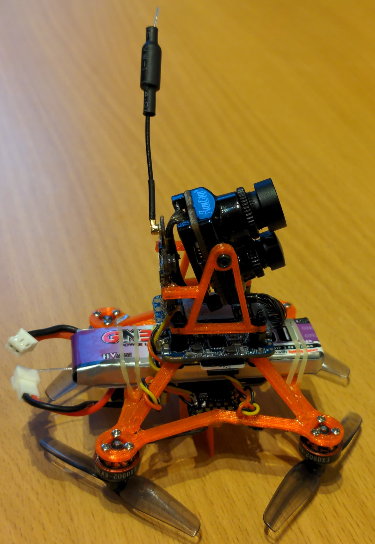
Here are the test indoor videos from the actual HD camera. Apologies for the mess at home
The weight is 56g with a 850 mAh 1S battery, of which the camera is a large percentage. The hover current is 5-6 amps with 0802 19000kV motors and 51mm props.
The current awkward build is a pusher because the FC has a USB port pointing downwards, where a battery would be an ideal option. Due to this I had to add an idiotic support, so that it does not spin on the ground while arming. However, a Throw initial mode will probably work better
Good job!
In order to use all the advanced functions of arducopter, will you also mount gps and compass? I think you will have to modify the frame and more …
That would be too heavy for this small guy The compass would also probably be jammed by the motors, as they are very close to everything onboard.
Maybe I will eventually do that if I find a more lightweight option for a camera. For that, I would probably drop an idea of having a 4K recording camera.
Also it may be a good idea to add a short-range lidar and optical flow instead. This would work better indoors, where GPS would be a non-option anyway.
I preferred to use a 3 "frame just to have more space for gps and compass (otherwise I would have used betaflight).
I also used optical flow. That’s actually light enough even for a whoop. Here you will find the type of optical flow and some test videos (at 25m).
I already have a sturdy full-blown 3" based on Matek H743-mini, which I really love.
I treat this small thing as a proof-of-concept whoop build, where I investigate how Ardu copes with such small sizes. As of now, I am in the process of tuning (and also frame redesign), and I can say that - probably due to high rotation frequencies - it is very easy to get a significant horizon drift if the D-terms are just a little too high.
Unfortunately, it seems that I have two out of four ESCs seriously damaged.
What is more, it seems to be like that from the beginning - in a hover, the outgoing RPMs were noticeably higher for them - but got worse recently, with one of them just stopping on any attempt to lift off. I will probably check whether the problem is indeed ESCs and not the motors, but overall that’s somewhat sad.