Hi. I am developing a custom bootloader for my Pixhawk 2.4.8. The first time I uploaded the bootloader. But it seems there was some error. The IO B/E led glows solid yellow. It was supposed to blink. I read that solid yellow of IO B/E means it is failure in bootloader. No I can’t upload any firmware onto my board. I tried Mission planner, QGC and waf build. I can’t upload/update new/old bootloader too. Can someone help me fix this? Please.
If that is the case you probably need to program the board with it in DFU using a dfu util or stm32cube programmer a google search will find them.
If found this for pixhawk, i dont own one but reading this looks like it will help , once you are in dfu upload the bootloader and you should be able to bring your board back to life. The stm32 bootloader cant be overwritten so unless you damaged it you will be able to recover.
malc
Thanks a tonne for responding. I am trying to flash using DFU. I am trying to read how to put the board in DFU mode. I will update you the results in a day at max. But I am curious. What is the difference in FMU B/E led and IO B/E? FMU B/E is blinking. But IO B/E is solid. I attached a pic.
I hope I did not damage the board somehow. Like I said. I will update you soon on DFU.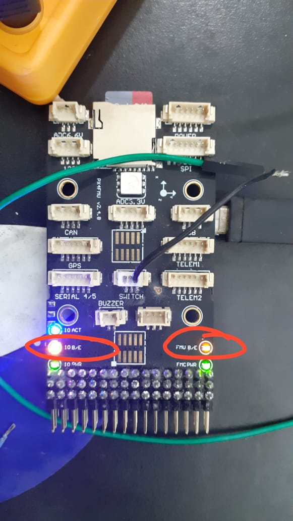
FMU is main processor the blinking one. The other could be for IOMCU which is the separate cpu that runs the pwm’s, safety switch etc.
IOMCU
Good day, just in case you need i can send you a new bootloader file with a small wiki so you don’t need use dfu or stlink… just let me know the version you need and i will prepare ir
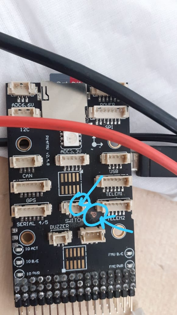
I tried to get the board into DFU mode. I found that the boot0 pin is already pulled up to 3.3 V. There is no potential difference between boot0 pin and the swtich’s VDD pin when I checked with multimeter. Can someone help?
BOOT0 should be pulled high and boot1 pulled low an2606 this will show you how to get into system boot for your cpu.
There is another way, if you look at debug on Ardupilot you will see the JTAG port connections you could attach stlinker and program via that way.
Thank you. Will checkout and let you know. But my fundamental doubt is… boot0 pin is already showing 3.3 Volts when I checked. That either means I am looking at the wrong pad. Please confirm the pin in the earlier image I attaced
Your looking for pattern 5 with an stm32f427
Got it. Thanks a tonne. Can you please confirm the boot0 pin in the image I attached? It is already at 3.3 V when I tested.
Have you checked out the schematics of your board?
I don’t own a pixhawk of any kind so can’t help. But if you are going to write a bootloader for your board you should know the hardware attached before you start otherwise you are doomed to failure. These are easy searches i have done.
sure. Thanks a tonne for the help. i’ll go through it. I’ll update you of the results. Thanks again.