I need help here. My pixhawk can’t boot and my PC can’t detect if after my first attempt to load arduplane firm into it.
The firmware installation fail after the process of live calibration of compass. After that my pixhawk cant boot, there is no sound and also the Main LED won’t light up anymore.
I have search the whole forum and found that the bootloader firmware might corrupted. How do i enter the DFM mode to install new good firmware. Hope someone can help.
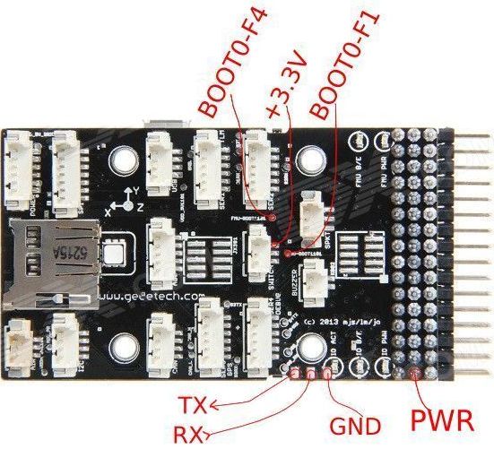
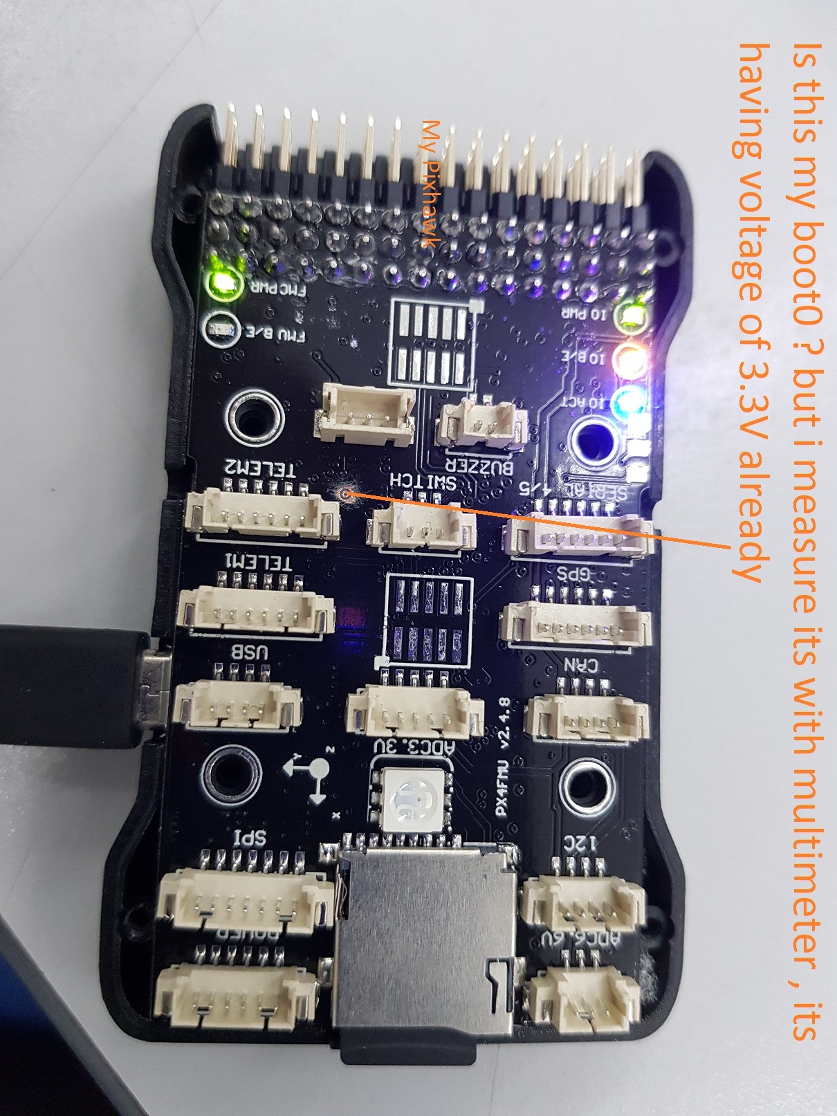
The first image is what i get from UAVOS. The second image is photo of my pixhawk FMU_V2. I am now having problem finding boot0 that i need to provide 3.3V+ in order to activate the DFU mode. My board seem a little different from the UAVOS reference photo. I have measure the point i circle in red. Its having +3.3V already. Any one can guide me which is the boot0 pin ? and where can i short it with 3.3V pin ?
If you look on the STM32 microprocessor on your Pixhawk, and guessing that you will see an “F4” as part of the number. If so, then the point you have marked in your photo is the correct Boot0 for F4.
Try connecting a pliers or tweezer from there to any 3.3v or 5v point while powering up the Pixhawk via the USB cable. If you have your drivers properly loaded on your PC, you can tell in the USB section of Device Manager that it can see the Pixhawk in DFU mode. Another easy way to do this is to use BetaFlight and it will automatically say “DFU Mode” in the upper right corner if it sees the Pixhawk. Then do a “Local Firmware” download.
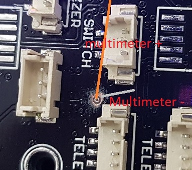
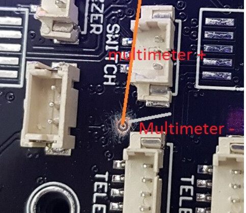
Thanks GreCovey. I measure the voltage of the mark point by referencing the common point to the switch +3.3 pin ( as guided by the first image i attached in this thread ) , the measure result is 0v instead of 3.3V. Therefore I try to measure the voltage of the marked point in a way which i have shown in the picture below and the result is +3.3v. If this is the boot0 then it already have 3.3v which is weird. Any comment on this ?
I have been working on this all morning and I cannot get BetaFlight to flash px4fmuv2_bl.bin. I have looked every where and I cannot find a .HEX version of this file. I NEED THIS ASAP… PLEASE
I bought a new 2.4.8 to replace the 2.4.6, so that aircraft is back in service. Because the 2.4.6 was partially functional I didn’t toss it out. I messed with it off and on for a few days and I kept getting the same results. Then I had a brain flash… I had been using my new Acer laptop and my recently upgraded desktop, but I hadn’t used my old Toshiba laptop.
So I pulled the Toshiba out of the closet, fired it up, launched MP, plugged in the 2.4.6, went to Initial Setup > Install Firmware and BOOM… it worked.
All three machines are running Windows 10. The “new” machines are running MP 1.3.62 and the Pixhawk is detected as a PX4FMU. The old Toshiba is running MP 1.59.3 and Windows detects the Pixhawk as a LegacyFMU.
For anyone reading this, here is a brief summary of what I did for a genuine 3DR Pixhawk.
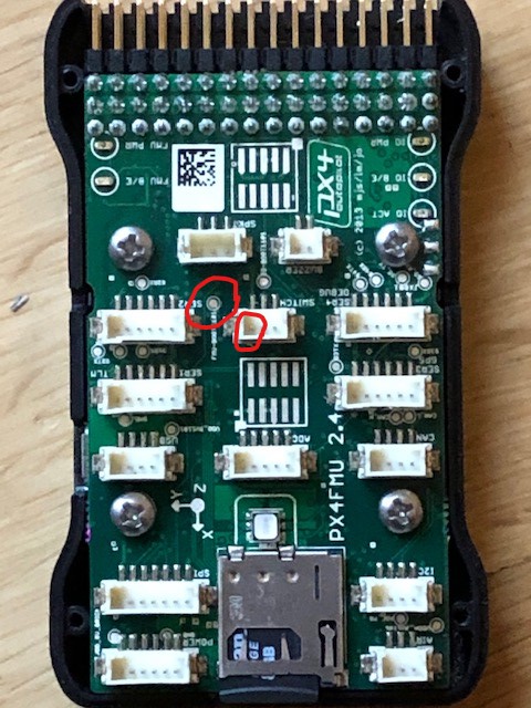
The pad identified above is correct and is labelled “FMU-BOOT” as specified in the wiki, however note that it is not in the place identified in the wiki, instead it is between the switch and telem2.
Adding a pull-down from +3.3v on the switch connector works well. I found that using +3.3v from the SPKT connected does not work.
Here is a picture with the pad and pull-down pin identified:
Hi Everyone,
As mentioned by “flamming Flex” the pin in multimeter is displaying as 3.3V. Is this the correct pin to shot it to VDD of 3.3Volts to enter DFU mode to flash the bootloader. Please let me know. Since in my pixhawk 2.4.8 hardware I am seeing that the pin is displaying 3.3Volts when measured on multimeter. Thank you in advance
Hi Felix,
Did you solve this mystery. I am seeing 3.3V on this pin on my multimeter. As per the schematic mentioned “https://github.com/ArduPilot/Schematics/tree/master/3DR” of pixhawk, the BOOT pin must be connected to GND, and we need to shot the VDD to BOOT0 pin to make the pixhawk to enter DFU mode. If you have solved this mystery, please tell me how did you solve it? Thank you in advance
I was going through the discussions to update the bootloader to from 4 to 5. If you are using pixhawk with 2.4.8 which supports 2 mb flash but can’t upload v3 firmware due to bootloader version 4, here is what worked for me: Download any fmuv3 firmware with bootloader which must be less than 1mb if you are using fmuv2. I downloaded ardusub firmware ver 4.1.2 with bootloader. Open mission planner and select custom firmware. select board type fmuv3 and flash this firmware. Reboot and connect by mavlink. Go to install firmware tab and it will now show “update bootloader” click at and bootloader will be upgraded. You can now flash full firmware with all its functionalities.